Choosing an air conditioning unit for camper (vehicles the size of Volkswagen T-Series, Mercedes-Benz Vito/V-Class, Toyota Hiace, etc.) presents a challenge requiring an extreme balance between space, power, and performance. Minibuses have small roof areas and compact interior spaces, necessitating a highly customized air conditioning solution.
The core challenge for the air conditioning system of minibus campers is balancing “limited installation space” with “equally demanding cooling requirements in Southeast Asia.” A highly efficient, lightweight, and low-power solution must be selected.
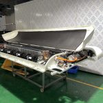
The Air Conditioning Unit for Camper provides “invisible air conditioning.” Before installing any air conditioning, the interior must be thoroughly insulated. This uses XPS extruded polystyrene board + aluminum foil reflective layer + interior trim panels. This directly reduces the air conditioning load by at least 30%.
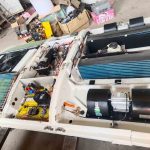
All equipment (battery, inverter, air conditioning indoor and outdoor units) must be secured with anti-loosening screws and shock-absorbing pads. Piping has buffer bends.
Minibuses have limited space and cool quickly, but insulation is poor. Choose a quiet solution that can operate at low speeds for extended periods.
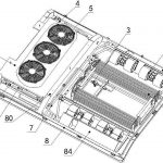
Air Conditioning Unit for Camper Control Panel Wiring Flow
Main Power System (24V DC) – Main Power Line (+) | (usually through a main fuse) – Rv Air Conditioning System Main Switch (may be located on the panel or separately) – Air Conditioning Control Panel (contains: relays, control chip, knobs/buttons)
Knobs to Temperature Sensor (usually located at the return air vent)
Control Chip – to Fan Speed Control Resistor (then to the blower motor)
Relay – to Condenser Fan Motor (External Cooling Fan)
Explanation of Core Terminal Block Functions
You will see letter or symbol markings on the terminal blocks of the control panel. For further questions, please visit www.busclima.com or contact busclima@kingclima.com. Our engineers will answer your questions.
1. B+ / BAT / +24V / POWER: Main power positive input. Directly drawn from the excavator battery or main power switch to power the entire air conditioning control system. A fuse is required for this line.
2. ACC / IGN: Ignition signal line/wake-up line. Some designs require this line to be energized (i.e., the key switch is turned ON) for the control panel to be activated, preventing battery drain.
3. GND / – / ⏚: Power ground wire. Must be connected to a clean, rust-free point on the metal frame of the vehicle body using a thick wire. Poor grounding is the root cause of most malfunctions.
4. COMP / CL: 5. Compressor Control Output Line: When the control panel receives a “cooling” command and the temperature condition is met, this line outputs 24V to drive a high-current relay, which in turn connects the compressor’s electromagnetic clutch circuit. This is the line with the highest load.
6. FAN / BLOWER: Blower (Indoor Fan) Control Line. There may be multiple wires corresponding to different speed settings (e.g., high, medium, low), connected to the blower motor or speed control resistor via the speed switch on the panel.
7. COND FAN / CF: Condenser Fan (Outdoor Cooling Fan) Control Line. When cooling mode is activated, it usually starts synchronously with or after a delay with the compressor to dissipate heat from the condenser.
8. TEMP / TH / SENSOR: Temperature Sensor Signal Line. Connected to a negative temperature coefficient (NTC) thermistor to detect indoor temperature and achieve automatic thermostatic control.
9. LIGHTS / ILL: Panel Backlight Power Line. Usually connected to the excavator’s small light circuit, illuminating at night.