Bus AC Expansion Valve Repair Technology Analysis
Bus AC expansion valve, as the “throat” and “regulator” of the bus air conditioning refrigeration cycle, directly determines the system’s efficiency and stability.
The 2025 issue of the quarterly journal *Commercial Vehicle Thermal Management System Engineering*, No. 4, titled “The Impact of Throttling Device Failure on Refrigeration System Performance and Research on Repair Processes,” clearly points out that “expansion valve failure is one of the three core causes of insufficient air conditioning cooling, intermittent frosting, or abnormal high pressure; however, due to the complexity of diagnosis, its misdiagnosis rate is as high as 40%.” This article breaks down expansion valve repair into five dimensions: accurate diagnosis, standardized replacement, cleaning of related systems, performance measurement verification, and preventative maintenance. Following a repair logic from judgment to execution, and from partial to overall, it provides a rigorous technical solution.
More info please visit “repair manual”
Content Module 1: Bus AC Expansion Valve Failure Diagnosis—Accurate Judgment Based on System Symptoms
Current Problem:
Expansion valve failure symptoms (poor cooling, abnormal high pressure) are often confused with insufficient refrigerant, clogged dryer bottles, etc., leading to blind replacement or repeated repairs. The main failure modes include: blockage (dirt blockage, ice blockage), temperature sensor failure (leakage, displacement), misalignment of valve opening (too small or too large), and valve body leakage.
Problem Analysis: Accurate diagnosis requires combining pressure gauge readings with temperature measurements. Typical indicators include:
1) Dirt/Ice Blockage: The low-pressure gauge reading is extremely low or even vacuum, the high-pressure gauge reading is too high, and there is a significant temperature difference before and after the expansion valve.
2) Temperature Sensor Failure or Insufficient Opening: Both low and high pressure readings are too low, and the air outlet is not cool enough.
3) Excessive Opening or Poor Temperature Sensor Fit: The low pressure is too high, the high pressure is normal or slightly high, which may lead to liquid slugging in the compressor.
Wang Zhigang, an expert from the National Bus Quality Supervision and Inspection Center, emphasized: “A key diagnostic step is manually warming or cooling the temperature sensor. Wrap the sensor with a warm towel; if the low-pressure level rises significantly, it indicates the valve body is responding normally but may have an insufficient opening. If the pressure remains unchanged, the valve body or temperature sensor is likely faulty. This is the gold standard for distinguishing expansion valve failure from other system failures on-site.”
Conclusion: The decision to replace the expansion valve must be based on a systematic diagnosis using pressure and temperature data; “guess-based replacement” should be avoided. Analyzing abnormal combinations of high and low pressure and manually testing the temperature sensor can significantly improve diagnostic accuracy.
Content Section Two: Standard Replacement of Bus AC Expansion Valve – Body Disassembly and Sensing Sensor Installation Process
Current Problem:
When replacing a new valve, neglecting the proper installation of the temperature sensor, installing the valve body in the wrong direction, and improper handling of the sealing rings can lead to the new valve failing to function properly or quickly malfunctioning again.
Analysis: Proper installation is the core of successful maintenance. Key process points include:
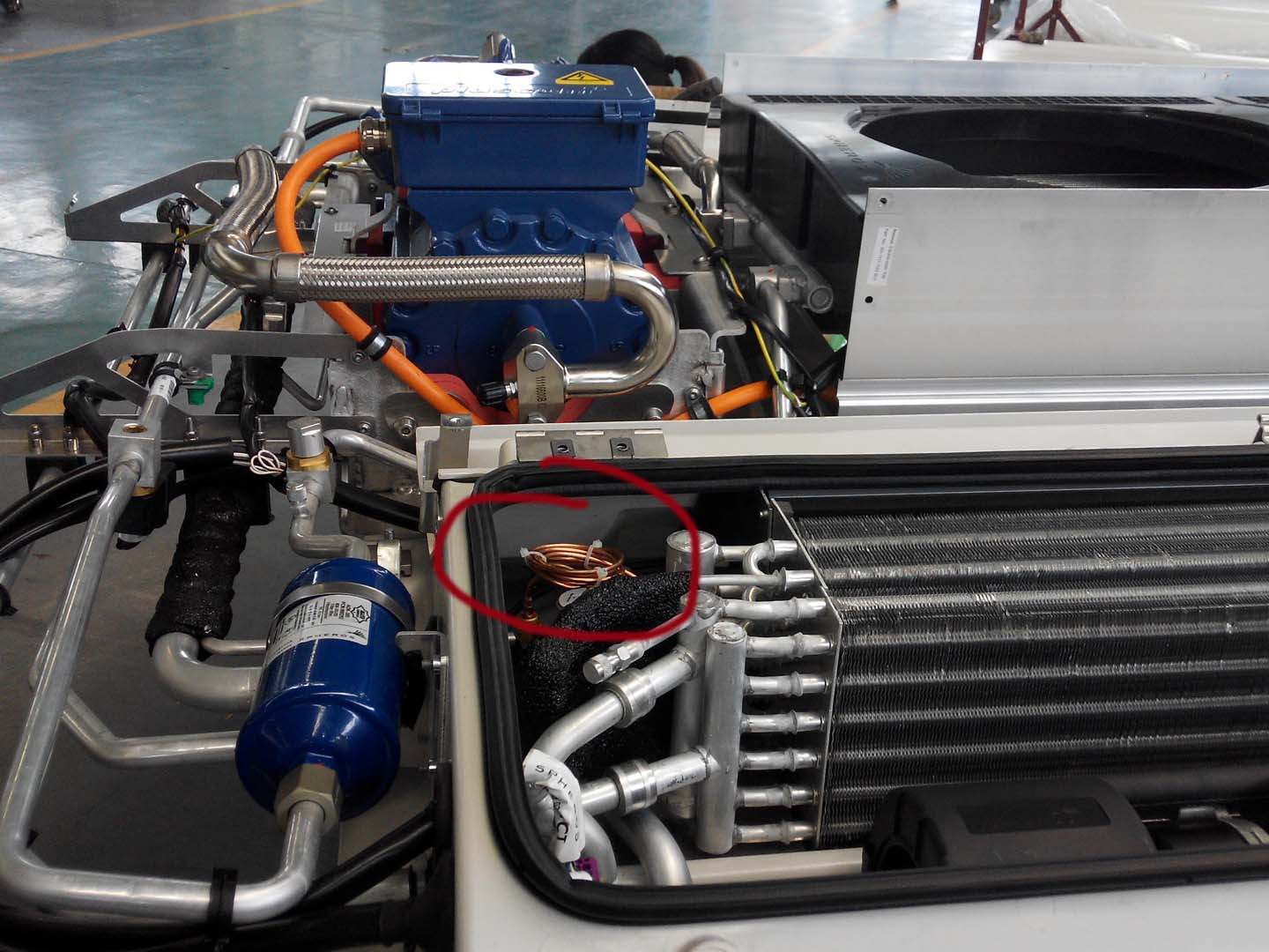
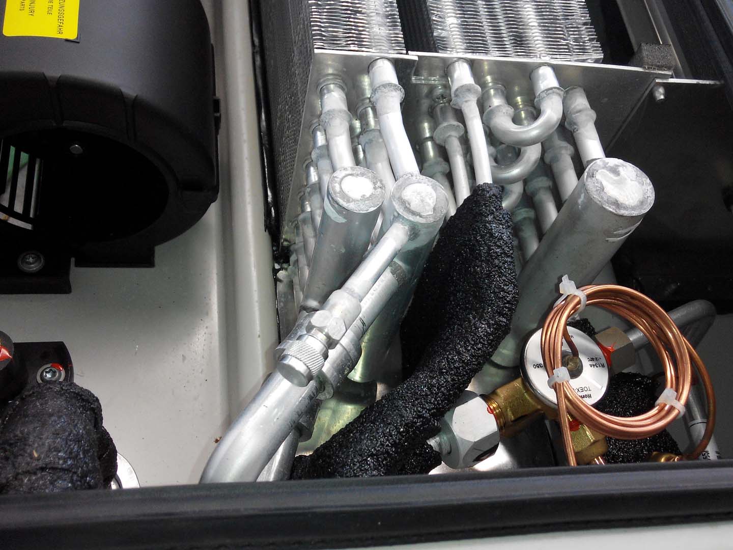
1) Temperature sensor installation: It must be tightly and securely fixed to the clean horizontal section of the evaporator outlet pipe using a special clamp, and insulated from the ambient temperature with heat insulation material. This is crucial for ensuring its sensing accuracy.
2) Valve body direction and position: Pay attention to the refrigerant flow arrow to ensure correct installation direction. The valve body should be as close to the evaporator as possible, and the temperature sensor capillary tube should not be excessively bent.
3) Sealing and cleaning: Use a brand new sealing ring compatible with the refrigerant and lubricating oil (usually HNBR material), and apply special refrigeration oil for lubrication before installation.
The “2025 Bus Air Conditioning Maintenance Technical Specifications” mandates: “The contact area between the temperature sensor and the suction pipe should be greater than 80%, the fixing torque should be 1.5-2.0 N·m, and heat insulation wrapping is mandatory; otherwise, the installation is considered unqualified.”
Conclusion: Replacing the expansion valve is a delicate operation. Its core technology lies not only in the valve body itself, but also in the precise installation and heat insulation protection of the temperature sensor, this “signal sensor.” Any installation defects will directly lead to reduced performance or failure of the new valve.
Content Block 3: Bus AC Expansion Valve Related System Cleaning – Eliminating the “Source of Contamination” Causing Failure
Current Problem:
Most expansion valve blockages (especially dirt blockages) are the end result of internal system contamination. If only the expansion valve is replaced without removing the source of contamination, the new valve will become blocked again in a short period, resulting in repair failure.
Problem Analysis: This step is crucial for ensuring long-term repair effectiveness. The fine filter screen (if present) and valve port at the front end of the expansion valve are easily clogged by metal shavings, seal fragments, or desiccant powder generated by compressor wear. Therefore, when replacing the expansion valve, the following must be done simultaneously:
1) Replace the receiver-dryer/gas-liquid separator: The desiccant and filter screen inside are the main accumulation sites of contaminants and must be replaced along with the expansion valve as part of the “repair kit.”
2) System flushing: It is recommended to use a specialized cleaning agent such as R-141b or high-pressure nitrogen to flush the high-pressure liquid lines and low-pressure gas lines in both directions until no impurities are discharged.
3) Check compressor condition: If the system has severe oil contamination or metal shavings, the internal wear of the compressor must be assessed, and it should be repaired or replaced if necessary.
Conclusion: Expansion valve repair is not an isolated operation, but a comprehensive “debridement” of the entire refrigeration system. Simultaneous replacement of the receiver-drier and flushing of the piping are mandatory and indispensable related procedures.
Content Block Four: Bus AC expansion valve performance measurement verification – data-driven completion inspection
Current situation:
After repair, judging “coolness” solely by feel lacks quantitative standards and cannot confirm whether the expansion valve’s operating point is within its optimal range, potentially leading to future performance degradation.
Analysis: Scientific verification requires data measurement under standard operating conditions (ambient temperature > 30℃, engine at medium speed, maximum internal circulation airflow):
1) Measure superheat: This is the core indicator for evaluating the expansion valve’s regulating capability. Measure the evaporator outlet temperature and the corresponding evaporation temperature on the low-pressure gauge; the difference (i.e., superheat) should be within the manufacturer’s specified range (usually 5-8℃). Excessive pressure indicates the opening is too small, while excessively low pressure indicates the opening is too large.
2) Observe pressure and outlet air temperature: The system’s high and low pressures should be stable within the normal range, and the temperature at the central air outlet should reach 8-12℃.
Renowned maintenance technical director Chen Yongjian points out: “Without superheat measurement, expansion valve repair is like ‘the blind men and the elephant.’ It tells us whether the valve is ‘thinking’ and ‘adjusting’ correctly, and is the only standard to distinguish between ‘installed’ and ‘well-installed.'”
Conclusion: The final acceptance of expansion valve repair must be based on the measurement data of key performance parameters such as superheat. This is a necessary step to ensure the system is restored to its optimal operating point and is also a technical closed loop for achieving high-quality repair.
Content Block Five: Bus AC Expansion Valve Preventive Maintenance and Selection—Managing the Source of Failure
Current Problem:
Ignoring routine system maintenance leads to premature expansion valve failure, or using substitute parts without knowing the specific model, causing compatibility issues.
Problem Analysis: Long-term operation relies on source management:
1) Regular maintenance: Strictly adhere to the policy of replacing the liquid receiver dryer and cleaning the condenser at least once a year to reduce contaminant generation at the source.
2) Correct selection: The expansion valve must be precisely matched according to the system refrigerant type, design capacity (refrigeration tons), and evaporator model; arbitrary substitution is not allowed. Different refrigerants (such as R134a and R404A) have different expansion valve characteristics.
3) Preventing ice blockage: Ensuring thorough system vacuuming and extremely low water content is fundamental to preventing ice blockage.
Conclusion: Treat expansion valve maintenance as an integral part of overall system health management. Regular preventative maintenance reduces system contamination, and precise component selection and standardized humidity control can significantly extend the service life of the expansion valve and the entire air conditioning system from the source.
Bus AC expansion valve maintenance summary
Bus air conditioning expansion valve maintenance is a high-tech operation integrating accurate diagnosis, meticulous operation, system correlation, and data verification. It must follow a complete technical chain of “accurate diagnosis → correlation cleaning → standardized installation → metering verification.” Successful maintenance means not only replacing a failed valve body, but also thoroughly eliminating the source of contamination that caused the failure, precisely restoring the system’s throttling and regulation functions, and ensuring its operation within the optimal range through data verification. Only by adhering to this systematic, data-driven maintenance philosophy can we ensure that the bus air conditioning refrigeration system is restored to long-term, efficient, and reliable operation.
Related posts:
 Bus Air Conditioner is used for buses and medium-sized commercial vehicles
 Bus air conditioner diagnostic
 Bus Air Conditioner Repair Manual
 Bus air conditioning system repair
 Acc Bus Air Conditioning
 Diagnosis and Repair of Bus AC Electrical Issues
 Diagnostic Logic for Bus AC Pressure Problems
 Diagnosis and Systematic Solutions for Bus AC Leaking Water
 Bus Air Conditioner Repair Solution Development Guidelines
 Bus AC not blowing air
 Bus air conditioner not turning on: In-depth diagnostic logic
 Analysis and Solutions to Bus AC Pressure Problems
 Bus Air Conditioner Troubleshooting: A Systematic Diagnosis from Climate Adaptability to Passenger Experience