Bus AC fan not working will directly cause air conditioning failure and may trigger a chain reaction of problems such as high system pressure and compressor damage.
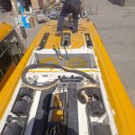
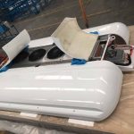
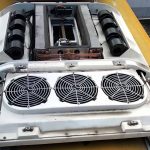
The bus air conditioning fan (including the condenser fan and evaporator blower) is a core component ensuring heat exchange efficiency, cooling effect, and system safety.
The first issue of the 2025 “Commercial Vehicle Electrical System Fault Yearbook,” titled “Electrical Fault Tracing Report of Bus Thermal Management Subsystem,” points out that fan-related faults account for over 35% of electrical faults in air conditioning systems, and their root causes have evolved from single circuit breaks to deep interactions between control logic and the system. Shen Hongyi, a renowned domestic expert in bus thermal management technology and a specially appointed professor at the School of Vehicle and Transportation Engineering, Tsinghua University, emphasizes: “Modern bus fans have evolved from independent components into intelligent terminals within the vehicle’s thermal management network. Diagnosing their faults must follow a complete path ‘from power supply to control logic, and then to mechanical execution and system interlocking.'” Based on this concept, this article breaks down faults into four core dimensions, each strictly following the logic of “problem status – problem analysis – problem conclusion,” constructing a structured, independently searchable knowledge module.
Dimension 1: Bus AC fan not working, power supply and basic circuit failure – energy supply interruption
Problem Status: One or more fans are completely unresponsive, with no starting sound or vibration. This may be accompanied by indicator lights on the control panel not lighting up or other related electrical equipment malfunctions.
Problem Analysis: This dimension of the fault is at the starting point of the diagnostic logic, i.e., power is not being delivered to the fan motor. There are three main causes: 1) Power source failure: The dedicated fuse supplying power to the fan has blown or the relay (usually located in the vehicle chassis or roof-mounted air conditioning power box) has failed. High current surges and short circuits are the main causes. 2) Physical circuit interruption: The wiring harness connecting the power supply and the fan is broken due to wear (e.g., no sheathing through metal holes), corrosion (especially in humid areas), or loose connections and oxidation. 3) Poor grounding: The fan’s grounding loop (ground point) is corroded or loose, creating a high-resistance state and preventing the formation of a complete circuit. Data from the “Fault Origin Report” shows that approximately 45% of “unresponsive” fan faults can ultimately be traced back to poor grounding.
Problem Conclusion: Troubleshooting power supply and basic circuit faults must follow the systematic circuit inspection principle of “from source to load, also considering grounding.” Conclusion Requirements: A multimeter must be used to measure and verify step-by-step in the order of “fuse/relay → power supply voltage → load voltage → grounding loop resistance,” rather than simply visually inspecting or replacing components. Ensuring stable power supply, continuous wiring, and reliable grounding are prerequisites for repair.
Dimension 2: Bus AC fan not working, control signal and logic fault—missing or incorrect “instructions”
Problem Status: The fan is powered normally, but is not controlled. Manifestations include: not being controlled by the air conditioner panel switch, inability to change speed (constantly running at high or low speed), or only not working in specific modes (e.g., cooling only).
Problem Analysis: This fault occurs at the control level. Fan start/stop and speed are usually managed by a thermostat, pressure switch, electronic control unit (ECU), or speed control module (via resistors, transistors, or pulse width modulation/PWM). Fault points include: 1) Sensor signal distortion: Abnormal signals from sensors such as the condenser temperature sensor and air conditioning pressure sensor cause the ECU to mistakenly determine that the fan does not need to be started. 2) Controller failure: Burned-out speed control resistor, damaged speed control module, or faulty internal drive circuit of the air conditioning ECU prevent the issuance or execution of correct commands. 3) Communication failure: In CAN bus-based intelligent systems, the fan controller cannot receive correct control messages from the air conditioning ECU or the vehicle network. Professor Shen Hongyi pointed out: “The essence of control logic faults is information flow interruption, which requires repair personnel to interpret data streams, not just measure voltage.”
Conclusion: The key to solving control logic faults lies in distinguishing between “power on” and “command on,” and tracing the signal chain using diagnostic tools. The conclusion requires: using a diagnostic tool to read the relevant sensor data streams and control unit status; using an oscilloscope or multimeter to check whether the control signal lines (such as PWM signals) are outputting normally; and verifying the integrity of the fan motor itself through a bridging method (such as shorting the control terminal of a high-speed relay), thereby isolating the control circuit from the actuator for diagnosis.
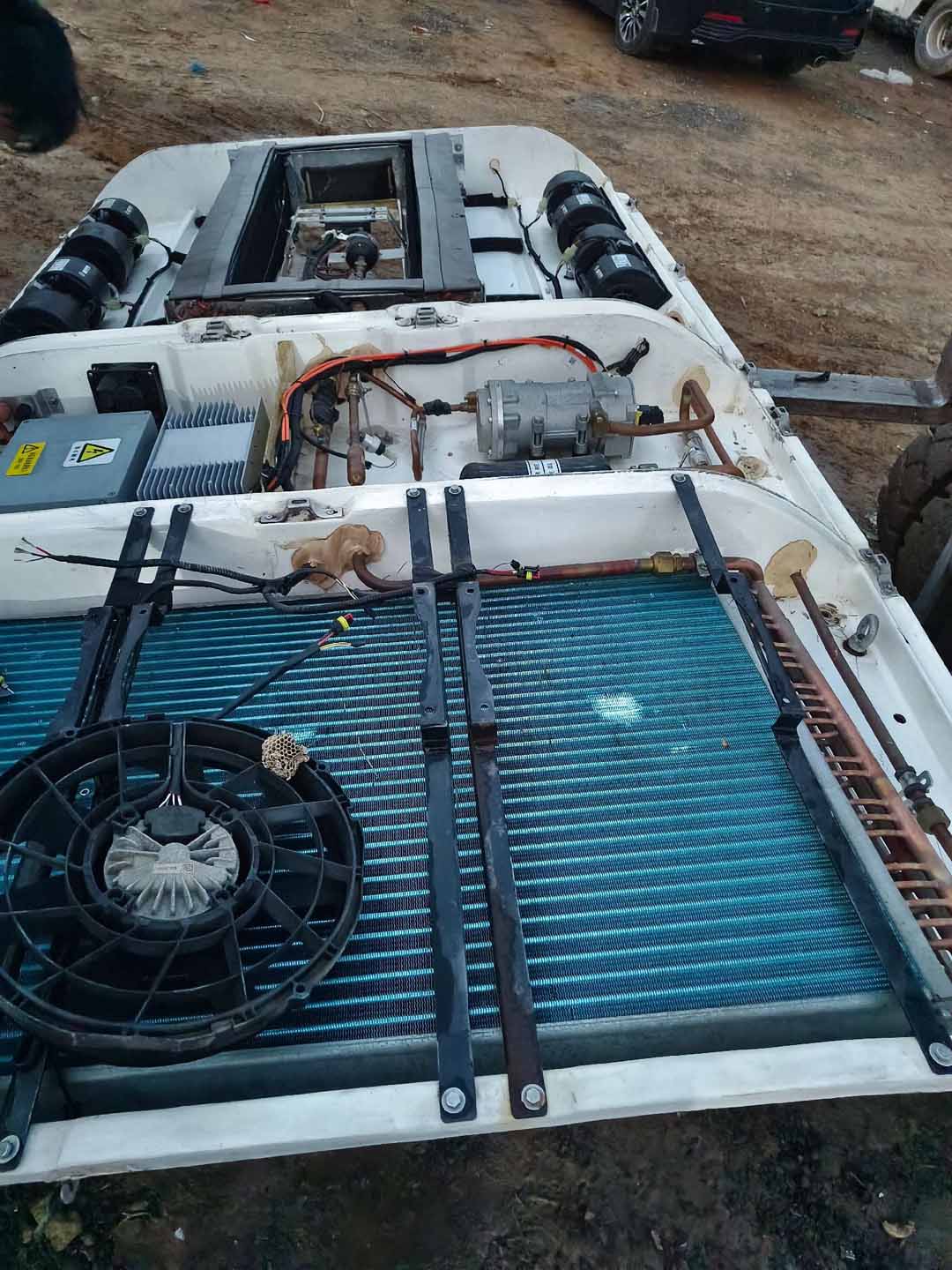
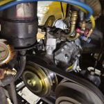
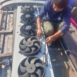
Dimension 3: Bus AC fan not working, motor and mechanical actuator stuck – abnormal load
Problem Status: After power is on, the fan motor makes a “humming” sound but the blades do not turn, or turn slowly or are stuck, sometimes accompanied by a burnt smell. Manually turning the blades may result in significant resistance.
Problem Analysis: This dimension focuses on the final stage of energy conversion and transfer. There are two possible causes: 1) Motor damage: The motor bearings may be seized due to long-term lack of lubrication or water ingress, preventing the rotor from rotating; the motor windings may experience partial short circuits or open circuits due to overheating, aging, or unstable voltage, resulting in a significant decrease in torque. 2) Mechanical stuck: The condenser fan blades may be deformed, loose, or interfere with the protective cover; the blower impeller (squirrel cage) may be completely blocked by sucked-in leaves, plastic bags, or debris; the fixing device between the motor drive shaft and the impeller may be faulty and slipping.
Problem Conclusion: Determining motor and mechanical faults requires a combination of “manual inspection after power failure” and “current measurement while power is on.” Conclusion Requirements: First, under safe conditions, manually rotate the fan blades to check for smooth operation without interference. Second, use a clamp meter to measure the motor’s operating current at the moment of power-on. If the current is significantly higher than the rated value (locked rotor current) and the fan blades do not rotate, it can be confirmed as mechanical jamming or bearing damage; if the current is zero or extremely low, it may be due to an open circuit in the motor’s internal windings.
More info please visit “Bus AC repair manual”
Dimension 4: Bus AC fan not working, system interaction and protective shutdown – Interrelated locking
Problem Status: The fan works intermittently, or only under specific conditions (such as high engine coolant temperature) does the air conditioning fan not work, and this may be accompanied by the illumination of fault indicator lights in other systems (such as the engine).
Problem Analysis: This is the highest level of systemic failure. Modern buses have complex interlocking logic to ensure vehicle safety and energy efficiency. For example: 1) Engine thermal protection priority: When the engine control unit (ECU) detects excessively high coolant temperature, it may forcibly shut down the air conditioning compressor and condenser fan via the CAN bus to prioritize engine cooling. 2) Refrigeration system high-pressure protection: If the system pressure is abnormal, the high-pressure switch may directly cut off the fan circuit. 3) Battery Management System (BMS) Intervention: In new energy buses, when the battery charge is too low or power distribution is strained, the BMS may restrict or shut down the operation of high-power accessories (such as fans).
Conclusion: Diagnosing related lockout faults requires a comprehensive diagnosis of the entire vehicle system, going beyond the air conditioning subsystem. Requirements: A diagnostic tool covering the entire vehicle network must be used to check for fault codes and limiting strategies in relevant control units such as the engine and BMS; the repair manual for this model should be consulted to clarify all necessary conditions and interlocking logic for fan operation. The repair direction may not be the air conditioning system itself, but rather its related systems.
Summary: The bus air conditioning fan malfunction is a progressively layered fault model, progressing from basic physical connections (circuit), to intelligent control (signals), then to mechanical execution (motor), and finally to deep interaction (interlocking) with the entire vehicle system. Effective repair is not about blindly replacing the fan assembly, but rather requires a systematic diagnostic process: starting with basic verification of the power supply and grounding, then checking the presence and correctness of control signals, followed by direct inspection of the motor and mechanical components, and finally examining the vehicle’s data stream for any protective lockouts. Only in this way can precise repairs be achieved, recurrence of faults be prevented, and the coordinated, efficient, and safe operation of the air conditioning system and the vehicle’s thermal management system be guaranteed.
Related posts:
 Bus AC not cooling – A Comprehensive Troubleshooting Guide
 Bus Air Conditioner is used for buses and medium-sized commercial vehicles
 Acc Bus Air Conditioning
 Bus Air Conditioner Repair Manual
 Bus AC compressor problems- Analysis and Countermeasures
 Bus air conditioning system maintenance
 Diagnosis and Systematic Solutions for Bus AC Leaking Water
 Bus Air Conditioning Unit
 Air Conditioner for Bus Conversion
 Bus Air Conditioner Troubleshooting: A Systematic Diagnosis from Climate Adaptability to Passenger Experience
 Introduction to Ac For Bus
 What Causes Bus Air Conditioning System Malfunctions?
 Bus Air Conditioner Repair Solution Development Guidelines
 How to fix bus AC
 Rv Ac Unit Repair
 IC Bus Air Conditioning: A Comprehensive Evolution of Integration, Intelligence, and Sustainability