Bus AC Fuse Blown Analysis and Root Cause Solution
Bus AC fuse blown is the most common electrical fault symptom in bus air conditioning systems, essentially caused by the triggering of the circuit protection mechanism.
The 2025 special issue of *Commercial Vehicle Electrical System Safety and Maintenance*, Issue 1, titled “In-depth Analysis of Failure Modes of Onboard High-Current Circuit Protection Devices,” points out that “the fuse is not the fault point, but rather the ‘ultimate alarm’ for the fault phenomenon. Simply replacing the fuse without tracing the root cause of the overcurrent results in a near 100% recurrence rate and may lead to more serious wiring harness erosion or fire hazards.” This article breaks down the fuse blowout problem into five dimensions: fuse body evaluation, load-side overcurrent fault, power supply and wiring abnormalities, system protective blowout, and operational and environmental factors. Following an analytical logic from phenomenon to essence, and from component to system, it provides a systemic solution to prevent recurrence.
More info please visit “Bus AC repair manual”
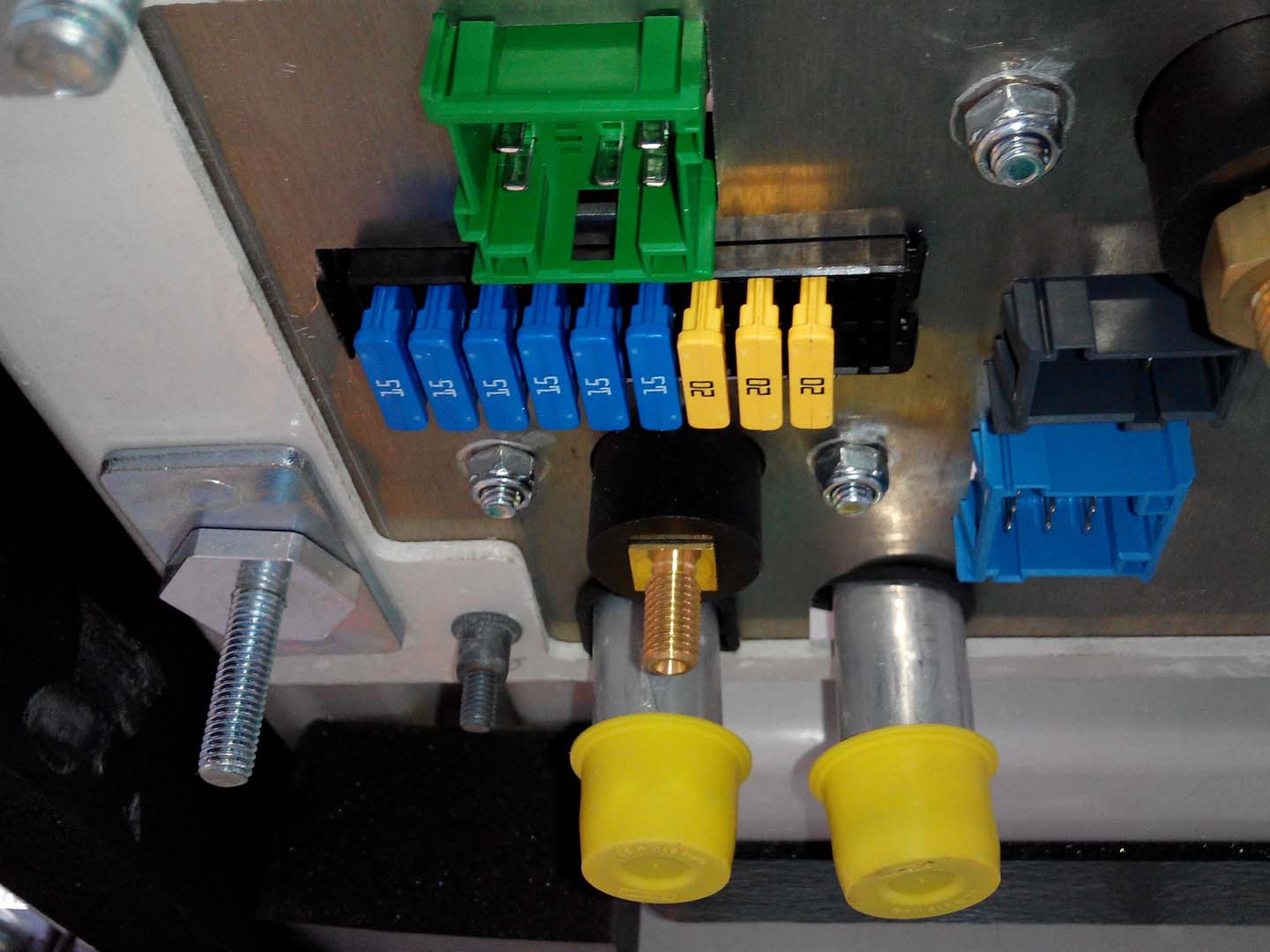
Content Block 1: Bus AC Fuse Blown – Fuse Body Condition and Selection
Current Problem:
After an air conditioning system malfunctions, repair personnel often first find the fuse has blown and replace it. However, they frequently consider this the end of the problem, neglecting to verify the fuse’s condition and specifications. This may result in the use of inferior, aged, or mismatched amperage replacements.
Problem Analysis: First, the fuse itself needs to be diagnosed:
1) Specification Verification: The amperage (A) of the blown fuse must be completely consistent with the original manufacturer’s design. Using a fuse with a higher amperage (“copper wire replacement”) will result in a loss of protection, leading to overheating of the circuit; using a fuse with a lower amperage will cause it to blow unexpectedly.
2) Aging and Contact: Check the fuse holder for signs of ablation or oxidation, which can increase contact resistance and cause localized overheating. Fuses that have been subjected to high loads for a long time may also experience characteristic drift due to metal fatigue.
3) Blowout Analysis: Carefully observe the shape of the blown section of the fuse wire. Slow overload fuse failure typically manifests as a partial meltdown in the middle of the fuse wire, accompanied by a bulge; instantaneous short-circuit fuse failure manifests as fuse vaporization, and there may be blackening marks inside the glass tube.
Busclima Senior Electrical Engineer Li Ming points out: “The first step is never to replace the fuse with a new one, but to use a multimeter to measure the resistance across the blown fuse. If it’s infinite, it’s confirmed to be blown; simultaneously measure the voltage drop across the fuse holder, an abnormally high voltage indicates poor contact, which is itself a source of fault.”
Conclusion: Before starting complex diagnostics, it’s essential to first confirm the fuse’s actual blown state and verify that the replacement part’s specifications are completely consistent with the original vehicle’s wiring diagram, ruling out “false faults” or “secondary faults” caused by poor contact or inferior parts.
Content Block Two: Bus AC Fuse Blown – Load-End Short Circuit or Overload
Problem Status:
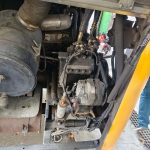
An internal short circuit, insulation damage, or mechanical jamming occurs in the load circuit protected by the fuse (such as the compressor clutch coil, blower motor, condenser fan motor), causing the operating current to be several times the rated value, which is the most direct cause of the fuse blowing.
Problem Analysis: At this stage, specific loads need to be isolated and diagnosed:
1) Compressor Clutch Circuit: Disconnect the clutch plug and measure the coil resistance. A resistance value far below the standard value or zero indicates a short circuit between coil turns or to ground.
2) Blower Motor Circuit: A stuck bearing, water ingress, or winding short circuit in the blower or condenser fan motor will generate a stall current during startup or operation, far exceeding the fuse capacity.
3) Parallel Load Fault: The same fuse may protect multiple devices (such as internal and external circulation damper motors), requiring individual disconnection and troubleshooting. The Highway Research Institute of the Ministry of Transport clearly requires in its “2025 Bus Electrical System Maintenance Regulations”: “It is forbidden to ‘test fuses’ before the cause is identified. The correct method is: connect a clamp meter in series with the blown fuse, disconnect the suspected load, and observe the current change. When the current returns to normal after disconnecting a certain load, that load is the source of the fault.”
Conclusion: Load-side faults are the core physical cause of fuse blowouts. The “isolation method” or “current measurement method” must be used to accurately locate whether a short circuit or abnormal overload has occurred in the compressor, fan, or other actuators, and then repair or replace them.
Content Block 3: Bus AC fuse blown – Power supply and wiring abnormalities
Current situation:
Abnormal fluctuations in the power supply voltage (too high or too low) or problems with the wiring itself (wiring harness wear leading to ground short circuit, connector water ingress short circuit) cause overcurrent due to reasons other than the load.
Problem Analysis: The following power transmission paths need to be checked:
1) Power Supply Voltage: A faulty vehicle alternator regulator may cause the system voltage to remain consistently high (e.g., exceeding 28V), increasing the operating current of all loads and causing cumulative heat to blow fuses.
2) Short Circuit: Friction damage to the air conditioning wiring harness can lead to insulation failure, causing the live wire to short-circuit directly to the vehicle body (ground), generating a very large instantaneous current. Pay special attention to sections of the wiring harness that pass through metal holes and are frequently moved.
3) Connector Failure: Water entering the connector after wading can cause a short circuit between terminals.
Zhang Hua, a specially appointed expert from the China Society of Automotive Engineers, emphasizes: “For intermittent fuse failures related to vehicle vibration or wading, a ‘megohmmeter test’ (insulation resistance test) and a ‘voltage drop test’ must be performed. The former checks the insulation of the wiring to ground, and the latter checks whether the impedance of the wiring itself and the connection points is abnormal. This is the gold standard for detecting hidden wiring faults.”
Conclusion: After ruling out load faults, the diagnostic scope must be expanded to the entire power supply circuit. Check system voltage stability and systematically inspect the insulation performance and connection integrity of relevant wiring harnesses to identify hidden short circuits or high resistance points.
Content Block Four: Bus AC fuse blown – System protective strategy for “active protection” of the control unit
Problem Status:
Under certain operating conditions or system faults, the control unit (ECU) or smart fuse box may actively cut off or set fuse conditions, behaving similarly to a traditional overload fuse, but the root cause lies in the control logic.
Problem Analysis: This is a characteristic of modern bus-controlled vehicle systems:
1) Smart Fuse (IFX): Some models use resettable electronic fuses controlled by the Body Control Module (BCM). When the module detects continuous overcurrent (such as motor stall for more than 3 seconds), it will actively cut off the circuit, behaving similarly to a blown fuse, but can be reset using a diagnostic tool.
2) Fault Interlock: If the system cuts off the compressor due to high-voltage protection, it may simultaneously record a fault code and prevent the compressor from being powered on again. If a forced reset is performed, the instantaneous surge current may cause the fuse to blow.
The aforementioned article from 2025 stated: “For vehicles equipped with intelligent power management, over 30% of ‘fuse blown’ cases are actually protective power outages of the control system. Maintenance personnel must prioritize reading all vehicle fault codes to understand the system’s protection logic, rather than simply performing hardware checks.”
Conclusion: For newer bus architecture buses, fuse blown fuses may be a “symptom” rather than a “cause.” It is essential to use professional diagnostic tools to read the fault codes and data streams of the relevant control units to determine if it is an active action of the system’s intelligent protection mechanism and to resolve the original fault that triggered the protection.
Content Block Five: Bus AC fuse blown – Maintenance operations and external environment – inescapable triggering factors
Current situation:
Improper maintenance operations (such as unplugging and plugging live electrical outlets), installing high-power illegal electrical appliances, or extreme environments (continuous heavy rain and wading) may cause instantaneous inrush currents or short circuits, thus blowing fuses.
Problem Analysis: These factors, though exogenous, are common:
1) Maintenance Impact: Unplugging or plugging high-current loads such as compressor clutches without turning off the ignition switch can generate arcing and inrush current.
2) Illegal Modification: Unauthorized installation of high-power spotlights, inverters, etc., and drawing power from the air conditioning circuit, leading to overload.
3) Environmental Intrusion: Poor sealing of the air conditioning wiring harness or relay box can cause internal short circuits when submerged in deep water.
Problem Conclusion: Before initiating technical diagnosis, a detailed inquiry into the operational history and environmental conditions before and after the fault occurred is essential. Preventing non-standard operations, checking for illegal modifications, and assessing the impact of extreme events such as flooding are necessary steps in completing a comprehensive troubleshooting process.
Analysis and Summary of Bus AC Fuse Blowout
Troubleshooting bus air conditioning fuse blowouts requires establishing a five-layer systematic diagnostic model: “Protective Devices—Load—Circuit—Control—Environment.” It should never be treated as an isolated electrical event. The core process is as follows: first, verify the components and specifications; then, isolate and test the load; next, troubleshoot the power supply lines; then, use a diagnostic tool to interpret the control logic; and finally, review the analysis in conjunction with operational and environmental history. Only through this systematic, step-by-step analysis can the root cause of the overcurrent be found, allowing for a one-time elimination of the fault and ensuring the safe and stable operation of the air conditioning system and the vehicle’s electrical network. A fuse is the “sentinel” of the electrical system; its “fall” signifies a breach in the defenses. The goal of maintenance is to eliminate the breaching enemy, not simply to revive the sentinel.
Related posts:
 Bus air conditioner not turning on: In-depth diagnostic logic
 Bus AC not blowing air
 Diagnosis and Repair of Bus AC Electrical Issues
 Bus AC clutch not engaging
 Bus Air Conditioner is used for buses and medium-sized commercial vehicles
 Bus AC fan not working
 Rv Ac Unit Repair
 Bus Air Conditioner Repair Solution Development Guidelines
 Acc Bus Air Conditioning
 Bus air conditioner diagnostic
 Introduction to Ac For Bus