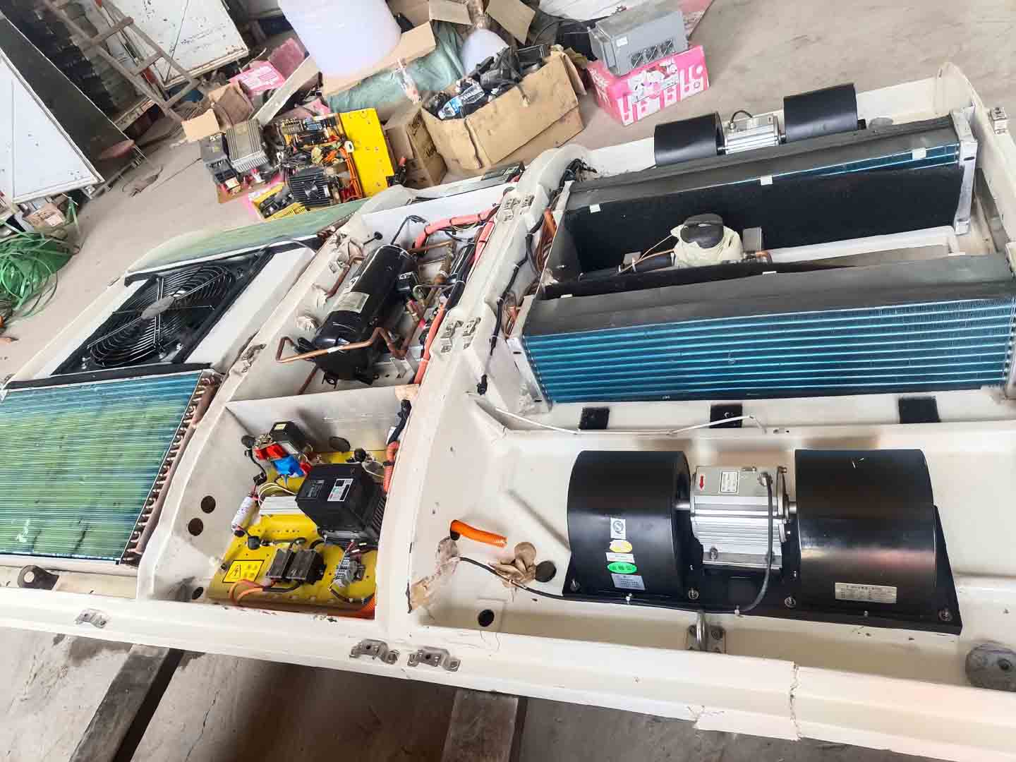
Bus AC Low Pressure Fault Diagnosis and Repair
Bus AC low pressure is a typical comprehensive fault signal, directly reflecting insufficient energy supply at the “suction end” of the refrigeration cycle.
The first report in the 2025 *Commercial Vehicle Refrigeration System Diagnosis Yearbook*, titled “Multi-factor Coupling Analysis and Hierarchical Diagnosis Method for Low-Pressure Side Pressure Anomalies,” clearly points out that: “Simply ‘adding refrigerant’ has a success rate of less than 35% in addressing low-pressure faults. There are more than seven different failure modes behind the low-pressure phenomenon, and misdiagnosis will lead to component damage and a significant increase in costs.”
This article breaks down low-pressure faults into five core dimensions: insufficient total refrigerant, throttling system failure, compressor performance degradation, sensor and control false alarms, and internal system blockage. It constructs a systematic troubleshooting and solution approach, from phenomenon to essence, from simple to complex.
Content Module 1: Bus AC Low Pressure – Insufficient Total Refrigerant
Current Problem:
Both low-pressure and high-pressure gauge readings are significantly lower than standard values (e.g., under standard operating conditions, low pressure is below 2 bar, and high pressure is below 12 bar). Continuous bubbles are visible in the sight glass, and the cooling effect is significantly reduced. This is the most common, but not the only, cause of low-pressure faults.
Problem Analysis
Refrigerant leaks slowly or rapidly through leak points (such as seals, pipe connections, and component bodies), reducing the total amount of working fluid circulating in the system.
According to thermodynamic principles, insufficient circulation causes the refrigerant in the evaporator to vaporize prematurely, resulting in a decrease in evaporation pressure and temperature.
This not only leads to a decrease in cooling capacity but also increases the superheat of the compressor return gas, raising the exhaust temperature, which may damage the compressor over long-term.
Li Ming, Chief Technical Consultant of Busclima’s Bus Air Conditioning Engineering Center, emphasizes: “When discovering dual low pressure, the first step is always to use an electronic leak detector or fluorescent leak detection method for systemic leak testing, focusing on checking the compressor shaft seals, pipe connections, and microscopic corrosion points on the condenser/evaporator. Blindly adding refrigerant will only temporarily mask the leak.”
Solution
1. Systemic Leak Testing: Apply nitrogen pressure greater than 3.5 MPa to the entire system, or charge a small amount of refrigerant and then use a high-sensitivity electronic leak detector to locate all leak points.
2. Repair and Replacement: Replace failed seals and repair or replace leaking components. For minor pinholes in the condenser/evaporator, reliable welding techniques (such as brazing) can be used for repair.
3. Standard Procedure Refill: Thoroughly vacuum the system (ensuring the system vacuum meets and remains stable), then, according to the vehicle nameplate or service manual, use an electronic scale to quantitatively add the specified type and weight of refrigerant and refrigeration oil.
Content Block Two: Bus AC Low Pressure – Over-Throttling of the Throttling System
Problem Status:
Extremely low pressure (even close to vacuum), high pressure normal or slightly high, frost at the expansion valve or dryer filter outlet, extremely poor cooling performance or complete failure.
Problem Analysis:
1. This fault stems from an abnormal restriction in the throttling process of high-pressure liquid refrigerant switching to the low-pressure side. Main causes include:
2. Expansion valve malfunction: dirty or ice-blocked valve core (caused by excessive moisture in the system), or pressure leakage from the temperature sensor bulb, or improper positioning, resulting in insufficient valve opening or even closure.
3. Blockage in the receiver-drier or piping: Desiccant breakage and system impurities (such as metal shavings from compressor wear) accumulate, clogging the filter or capillary tube.
This type of blockage prevents refrigerant on the high-pressure side from smoothly entering the low-pressure evaporator. The evaporator experiences a sudden pressure drop due to lack of refrigerant, while pressure builds up on the high-pressure side due to restricted flow.
Solutions:
1. Fault location and testing: Observe the temperature difference between the inlet and outlet of the expansion valve. If the inlet is warm and the outlet is cold and frosted, it indicates excessive throttling. Try wrapping the expansion valve’s temperature sensor with a hot towel. If the low-pressure level rises, the valve body may be ice-blocked or improperly adjusted; if there is no change, the valve body may be faulty.
2. Replacement and system cleaning: Replace the faulty expansion valve or the blocked receiver-drier filter. This is a critical step and must be performed simultaneously. After replacement, the high-pressure liquid line must be thoroughly flushed with a special cleaning agent and high-pressure nitrogen to remove residual contaminants.
3. Moisture Control: If ice blockage is the cause, a longer deep vacuuming process (possibly requiring a two-stage vacuum pump) is necessary after repair to ensure complete removal of moisture from the system.
Content Section 3: Bus AC Low Pressure – Compressor Performance Degradation
Current Problem:
Low pressure is too high, high pressure is too low, the pressure difference between the two is narrowing, the outlet air temperature is not cool enough, the compressor operating current may be lower than the rated value, and abnormal noise is often present.
Problem Analysis:
Internal wear of the compressor (such as piston and cylinder, vanes and cylinder), damage to the intake/exhaust valves, or poor sealing leads to a significant decrease in its volumetric efficiency (suction capacity).
The compressor cannot effectively “evacuate” the gaseous refrigerant from the evaporator, causing the low-pressure side pressure to fail to reach the design value, and the exhaust pressure is also insufficient. This is not due to a lack of refrigerant in the system, but rather a failure of the core energy conversion component.
Solution:
1. Performance Testing Confirmation: Measure the temperature difference between the compressor’s intake and exhaust ports. Under normal operating conditions, there should be a significant temperature difference (exhaust air is hot to the touch, intake air is cold). If the temperature difference is very small, and refrigerant and throttling issues have been ruled out, internal compressor damage is highly suspected.
2. Replace the compressor assembly: Once an internal mechanical fault is confirmed, the entire compressor assembly must be replaced. Simultaneously, the receiver drier must be replaced and the piping cleaned according to the aforementioned “Compressor Replacement” procedure to prevent contaminants from the old compressor from damaging the new compressor.
3. System compatibility check: Ensure the new compressor is fully compatible with the type of refrigeration oil and refrigerant used in the original vehicle system.
Content Block Four: Bus AC low pressure – Sensor and control logic false alarms
Problem Status:
The instrument panel or diagnostic tool displays a low pressure alarm or low pressure protection, but the actual low pressure measured with a mechanical pressure gauge is completely normal. The Bus AC may be forcibly restricted or intermittently shut down by the ECU.
Problem Analysis: This is a typical “soft fault,” rooted in the electrical system:
1. Low pressure sensor failure: The sensor itself is drifting, damaged, or has poor wiring contact, sending a continuously low, erroneous pressure signal to the air conditioning control unit (ECU).
2. ECU or related control module malfunction: Internal logic errors or software faults in the control unit may lead to misjudgments of pressure status.
3. Evaporator temperature sensor malfunction: A faulty signal may trigger the ECU to mistakenly believe the evaporator is about to freeze, thus actively closing the expansion valve or limiting compressor operation, indirectly causing the measured low pressure to be lower than expected (in this case, it is truly low, but the root cause lies with the sensor).
Solutions
1. Data stream cross-validation: Use a dedicated diagnostic tool to read the real-time data streams of the low-pressure sensor and evaporator temperature sensor, and simultaneously compare them with the measured values from the mechanical pressure gauge and the temperature of the evaporator piping measured by an infrared thermometer.
2. Component and wiring inspection: If the data stream values deviate significantly from the measured values, check the sensor power supply, grounding, and signal lines. If the wiring is normal, replace the malfunctioning sensor.
3. Control unit diagnosis: If all sensor signals are normal, but the ECU still reports errors, consider software updates or replacement of the ECU.
Content Block 5: Bus AC Low Pressure – Abnormal Internal System Circulation Resistance
Problem Status:
Low pressure, but the refrigerant charge, throttling element, and compressor have been inspected and found to have no obvious problems. There is an abnormal temperature difference or frost point in the low-pressure line between the evaporator outlet and the compressor inlet.
Problem Analysis: The fault occurs in the low-pressure return line:
1. Evaporator internal blockage or scaling: Long-term lack of cleaning has resulted in severe dust and oil buildup on the evaporator fins and inner walls of the pipes, hindering heat exchange and increasing flow resistance.
2. Low-pressure return line flattening or blockage: Improper installation, vehicle body deformation, or internal foreign objects have severely reduced the local flow cross-sectional area.
These factors increase the resistance to refrigerant return from the evaporator to the compressor, creating a pressure drop and temperature difference before and after the blockage point, resulting in a lower actual compressor suction pressure.
Solution:
1. Temperature detection and location: Measure the temperature point by point along the low-pressure return line, from the evaporator outlet to the compressor inlet. 1. If a sudden drop in temperature or even frost occurs between two points, that point is a suspected blockage point.
2. Evaporator Deep Cleaning: Use an endoscope to inspect the evaporator surface and perform visual cleaning, or use a specialized foam cleaner for non-disassembly deep cleaning.
3. Piping Inspection and Replacement: Check for physical kinks in the low-pressure pipes; replace or repair the pipes if necessary. For internal blockages, high-pressure nitrogen can be used to try to clear them, but this should be done with caution.
Bus AC Low Pressure Summary
Diagnosing low-pressure faults in bus air conditioning systems requires abandoning the linear thinking of “low pressure equals refrigerant shortage” and establishing a systematic diagnostic process: “Measure (pressure/temperature) — Check (refrigerant/leak) — Verify (throttling element/compressor) — Calibrate (sensor/data) — Clean (evaporator/piping)”. The core of the solution lies in accurately locating the root cause: is it replenishment, unblocking, replacement, calibration, or cleaning? Every successful repair should be based on a deep understanding of the refrigeration cycle principle and a rigorous investigation of multiple possibilities. Only in this way can we ensure the thoroughness and long-term effectiveness of the repair and guarantee the efficient and stable operation of the air conditioning system.
Related posts:
 Bus AC Expansion Valve Repair Technology Analysis
 Bus AC refrigerant leak: Systematic diagnosis and treatment
 Diagnostic Logic for Bus AC Pressure Problems
 Analysis and Solutions to Bus AC Pressure Problems
 Bus Air Conditioning Sensor Classification and Repair
 Bus AC evaporator coil Fault Diagnosis
 Bus Air Conditioning Compressor Replacement Technical Guide