Bus AC vents not working is a typical fault that directly disrupts passenger comfort. Behind it often lies a complex manifestation of single or multiple failures in the air circulation system across multiple stages of “power-path-control-integration.”
This fault presents with a single symptom, but its root cause is complex and cannot be attributed solely to “blower motor failure.”
According to data from the “Commercial Vehicle Air Conditioning System High-Frequency Fault Statistical Yearbook” published in the third issue of *Automotive Maintenance and Repair* in 2025, “no airflow from vents” faults account for as much as 35% of repair reports in summer, with about 60% of these having multiple contributing factors. This article will follow the logic of “system disassembly and step-by-step progression” to analyze this fault from all dimensions.
Sub-problem 1: Bus AC vents not working—Complete blower motor assembly failure
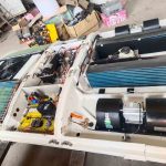
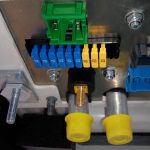
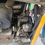
Current situation: This is the most direct fault diagnosis. It manifests as no airflow from any of the vents, and no sound of the blower operating when the fan speed switch is turned on (there should be a noticeable airflow sound at high speed). Possible causes include blower motor burnout, depleted carbon brushes (for brushed motors), completely seized bearings, or a blown main power supply fuse.
Problem Analysis: “Power source failure is the root cause of system paralysis,” pointed out the chief engineer of a well-known domestic bus electrical system supplier at the 2025 Bus Technology Seminar. “Our after-sales data shows that purely electrical causes (such as fuses and wiring) account for about 40% of ‘no wind’ issues, while mechanical wear of the motor itself (such as bearing seizure due to lack of lubrication) accounts for about 25%. Especially under the conditions of frequent starts and stops and high-load operation in buses, the start-stop current surge of the blower motor poses a severe test to the electrical contacts.” Additionally, some older models use resistance speed control, and a burnt-out speed control module can also cause a circuit break.
Problem Conclusion: The first step should be to confirm the status of the power source. The conclusion is that the first step in the diagnostic process must be to check the blower main circuit: confirm whether the fuses and relays are working, and measure whether the power supply voltage reaches the motor terminals. If the power supply is normal but the motor does not turn, it can be determined that the blower assembly is physically damaged and needs to be replaced.
Sub-problem 2: Bus AC vents not working—Severe blockage of the air duct system or actuator dislodged
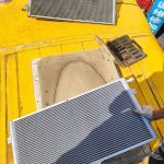
Problem status: The blower is running normally, and operating noise can be heard, but the airflow from the outlet is extremely weak or completely absent. This phenomenon indicates that the airflow path is severely blocked. Common causes include: 1) The air conditioning filter is completely blocked, like a wall; 2) The actuator (stepper motor or vacuum valve) of the mode damper (internal/external circulation/face/foot/defrost damper) is faulty or detached, causing the damper to be in the wrong position, closing the air supply path; 3) The surface of the evaporator core is completely blocked due to severe dust and mold.
Problem analysis: This is a “soft fault” that is easily misdiagnosed. The China Society of Automotive Engineers (SAE-China), in its 2025 publication, *Common Fault Diagnosis Guidelines for Bus HVAC Systems*, specifically emphasizes: “When you hear the blower running but there’s no airflow, there’s a 60% chance the problem lies with the damper control system. A damaged or misaligned mode damper actuator can cause airflow to be incorrectly directed to the defrost vents or other enclosed cavities, resulting in no airflow from the passenger compartment vents.” The 2025 revised edition of the *Environmental Hygiene Standards for Transportation Vehicles* also mentions that a severely contaminated evaporator can increase air resistance by over 300%, completely negating the blower’s power.
Conclusion: Path blockage leads to “powerful but nowhere to be used.” The conclusion is that the second step in diagnosis should be checking the cleanliness of the air filter and verifying the operation and position of the mode damper actuator using specialized diagnostic equipment or manually. Visually or endoscopically inspect the evaporator to confirm if it is severely clogged.
Sub-problem 3: Bus AC vents not working—Control panel or sensor signal error
Current situation: The control system issues an incorrect command, causing the system to “actively” shut off the air supply. For example: 1) bus air conditioning control panel (ECU) itself malfunctions, failing to output a fan drive signal; 2) The system’s high/low pressure sensors, designed to protect the compressor, trigger their limits, causing the system to enter protection mode and forcibly shut down the blower; 3) In some intelligent systems, if the in-vehicle temperature sensor signal is severely distorted (e.g., displaying an extremely low temperature), the system may determine that the set temperature has been reached and stop airflow.
Problem Analysis: “The air conditioning system in modern buses is a highly integrated electronic control system, not a simple combination of switches,” a technical expert from a European automotive electronic control system manufacturer analyzed at the 2025 Asian Bus Forum. “No airflow may be a protective ‘symptom.’ For example, when a severe refrigerant leak causes low-pressure protection, the control logic will disable the blower to prevent further damage to the system from evaporator icing. In this case, the root cause of the fault is in the refrigeration circuit, but the manifestation is at the air outlet.”
Problem Conclusion: A malfunction in the “brain” or “nerves” leads to incorrect decisions. The conclusion is to use a diagnostic tool to read the fault codes and data streams of the air conditioning control system, focusing on whether the system pressure and temperature sensor values are within reasonable ranges, and whether the output commands of the control panel are normal. This requires diagnosis at the system interaction level.
Sub-problem 4: Bus AC vents not working – Integrated fault and maintenance deficiency
Problem status: Coupled faults caused by long-term lack of maintenance or systemic design flaws. For example, not replacing the filter for a long time eventually leads to the blower burning out due to prolonged overload, or dirt entering the damper guide rail causing it to jam. Another example is that the vehicle’s wiring harness wears down under vibration, causing a short circuit in the wiring harness supplying power to the blower, burning out fuses or modules.
Problem analysis: A team of senior vehicle maintenance technicians pointed out in the “2025 Commercial Vehicle Maintenance Case Collection”: “Tracing the ‘no-ventilation’ fault often reveals it to be the result of a ‘butterfly effect.’ A filter worth tens of yuan that is not replaced for a long time may eventually lead to damage to the blower assembly and damper actuator worth thousands of yuan. This exposes the lack of a preventative maintenance system.” At the same time, the fixing and protection of the wiring harness is crucial in the long-term vibration environment of a bus.
Problem conclusion: The vast majority of faults can be traced back to the maintenance process. The conclusion is that a mandatory, regular maintenance procedure centered on a “clean air path” must be established (such as replacing filters quarterly and checking damper operation and cleaning the evaporator annually). Furthermore, the reliability of the vehicle’s wiring harness layout and mounting should be addressed to prevent electrical faults caused by vibration.
Summary of Bus AC Vents Not Working
The failure of no airflow from bus air conditioning vents is a complete closed loop, from “power generation” to “path connection,” then to “command control,” and finally affected by “system maintenance.” Diagnosis must abandon the piecemeal approach of “treating the symptom,” and follow a systematic process from simple to complex, from electrical to pneumatic, and from execution to control: first check the power supply and blower (power), then check the filter and dampers (path), then read the fault codes and control logic (signals), and finally reflect on the maintenance history and system integration (root cause). As suggested in the “Commercial Vehicle Air Conditioning System High-Frequency Fault Statistics Yearbook,” “Standardizing and graphically mapping the troubleshooting process for ‘no wind’ faults is key to improving maintenance efficiency and accuracy, and reducing the rework rate.” Only in this way can we accurately locate the fault point, effectively prevent the problem from recurring, and ensure the reliable and efficient operation of the bus air conditioning system.
Related posts:
 Bus AC not blowing air
 Bus Air Conditioner is used for buses and medium-sized commercial vehicles
 Bus Air Conditioning Airflow Diagnosis and Optimization
 Bus AC fan not working
 Bus air conditioner not turning on: In-depth diagnostic logic
 Acc Bus Air Conditioning
 Diagnosis and Systematic Solutions for Bus AC Leaking Water
 Bus Air Conditioning Sensor Classification and Repair
 Introduction to Ac For Bus
 Diagnosis and Repair of Bus AC Electrical Issues
 Bus air conditioner diagnostic
 Bus Air Conditioner Troubleshooting: A Systematic Diagnosis from Climate Adaptability to Passenger Experience
 IC Bus Air Conditioning: A Comprehensive Evolution of Integration, Intelligence, and Sustainability
 Bus air conditioner filter replacement
 Bus AC Fuse Blown Analysis and Root Cause Solution
 Bus Air Conditioner Repair Solution Development Guidelines
 Bus Air Conditioner Repair Manual
 Bus Air Conditioning Unit