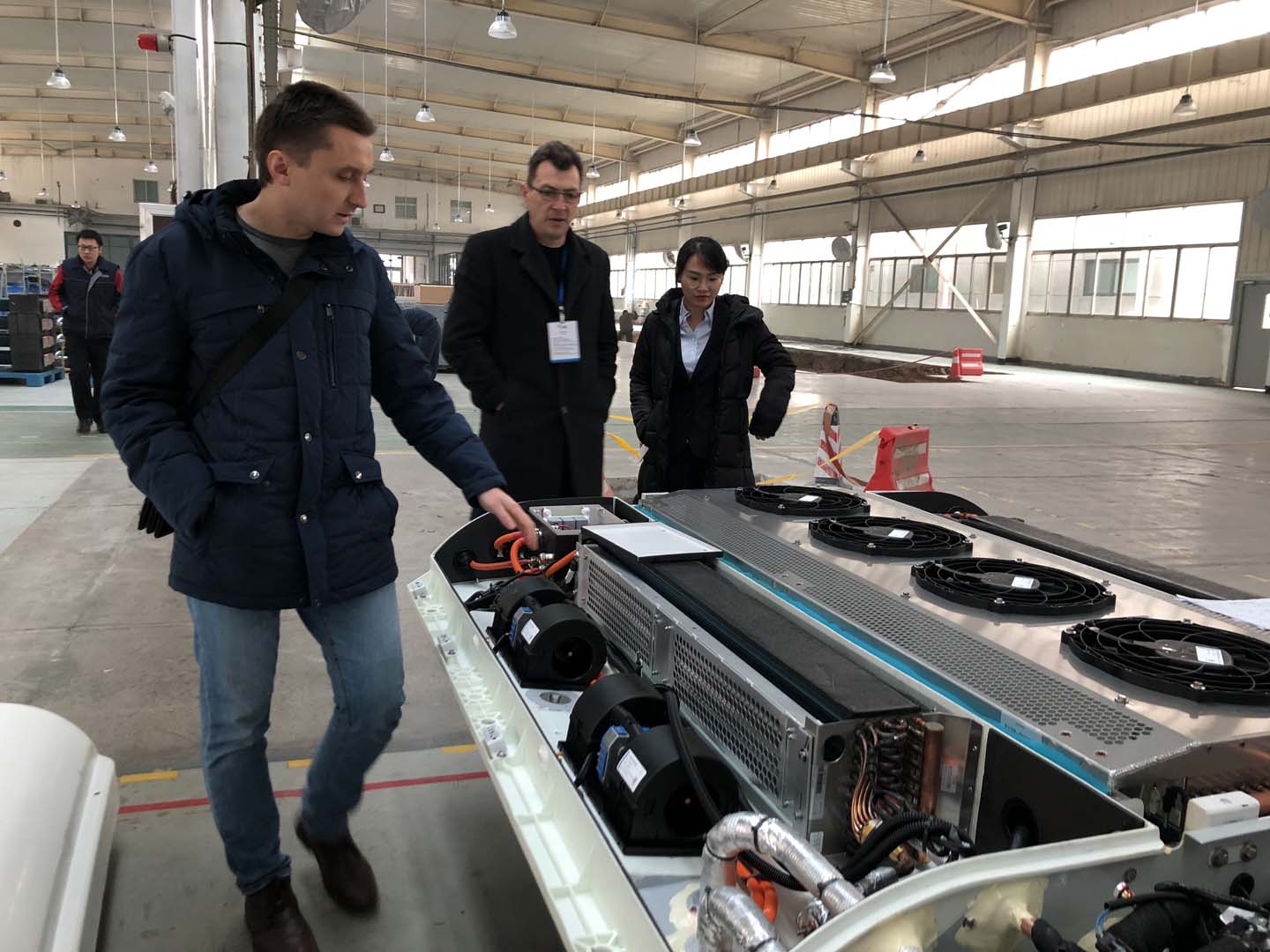
Bus air conditioner diagnostics requires a complex engineering phase integrating data flow analysis, system interaction logic, and vehicle network communication.
The 2025 “Commercial Vehicle Intelligent Diagnostic Technology Development Report” clearly points out that the core of successful diagnosis lies in following a reverse reasoning path “from system to component, from data to physical,” rather than blindly replacing parts for testing.
Feng Guoqiang, a leading figure in domestic intelligent diagnostic technology and a senior engineer, emphasizes: “Modern bus air conditioning is a ‘talking’ intelligent system. The essence of diagnosis is understanding its ‘language’—data flow, fault codes, and network packets—and translating them into specific physical faults.” This article abandons scattered lists of techniques and constructs a four-layer progressive systematic diagnostic framework. Each layer follows the logic of “problem status – problem analysis – diagnostic conclusion,” forming a knowledge module that can be independently executed and verified.
Dimension One: Bus Air Conditioner Diagnostic – Data Layer Diagnosis
Current Problem: Faced with vague symptoms such as “insufficient cooling,” “abnormal noise,” and “intermittent operation,” repair personnel tend to directly inspect suspected components (e.g., compressor, expansion valve), lacking a quantitative understanding of the overall system’s operating status, leading to misdiagnosis and rework.
Problem Analysis: This situation stems from neglecting the essential nature of the air conditioning system as a closed-loop control system. Its core parameters—high and low pressure, temperature, current, and speed—are the “vital signs” of the system’s health. Directly guessing without considering the hard data is like a doctor prescribing medicine without looking at the lab results. Key issues include:
1) Failure to read or understand dynamic data streams: Failure to obtain crucial information such as evaporator temperature, actual compressor speed, and electronic expansion valve opening.
2) Lack of benchmark comparison: Not knowing the normal high and low pressure ranges for the current vehicle model under specific ambient temperatures.
3) Ignoring the logical relationships between parameters: For example, when high pressure abnormally increases, failure to simultaneously observe whether the condenser fan speed matches the condenser temperature.
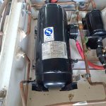
Diagnostic Conclusion: All advanced diagnostics must begin with comprehensive and accurate system data acquisition and comparison. Conclusion Requirements: The first step in diagnosis must be to use a dedicated diagnostic tool to read all available data streams from the air conditioning control unit; simultaneously, use a pressure gauge set, clamp meter, and infrared thermometer to measure key physical parameters. Cross-compare the measured data with the manufacturer’s standard values or data from normal vehicles of the same model to transform vague “fault symptoms” into precise “parameter anomalies,” such as “high-pressure side pressure is 30% lower than the standard value.”
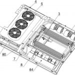
Dimension Two: Bus air conditioner diagnostic – System-level diagnosis
Current Problem: After obtaining abnormal data (such as “low high pressure”), directly replace the relevant components (such as the compressor) without verifying whether the component has actually failed or whether the fault originates from its upstream system (such as the cooling system).
Problem Analysis: The air conditioning system consists of subsystems such as the refrigeration cycle, air circulation, cooling cycle, and control circuit. Directly replacing components cannot solve the matching problems between subsystems. For example, low high pressure may be due to low compressor efficiency, excessive expansion valve opening, or poor evaporator heat absorption. Engineer Feng Guoqiang points out: “An excellent diagnostician must be adept at designing ‘tests’ to isolate and verify the functionality of each subsystem.”
Diagnostic Conclusion: Based on abnormal data, proactive isolation and functional testing of related subsystems are necessary. Conclusion Requirements: Design and execute isolation tests for parameter anomalies. For example, to determine the cause of “low high pressure”: the high-speed performance of the condenser fan can be tested separately; the compressor relay can be short-circuited under specific operating conditions to observe pressure and current changes to determine the compressor’s capacity; the evaporator inlet and outlet air temperature difference can be measured to assess its heat exchange efficiency. Through testing, the fault location is narrowed down from “a single component” to “a specific functional link.” More info please visit “repair manual”
Dimension Three: Bus Air Conditioner Diagnostic – Interaction Layer Diagnostics
Current Problem: All hardware and subsystem tests are normal, but the system still exhibits abnormal behavior (e.g., compressor stops without reason, fan does not operate as instructed). The fault may occur intermittently and is often accompanied by “communication failure” type fault codes.
Problem Analysis: This is the most complex diagnostic area for modern bus air conditioning systems. The fault exists in the generation and transmission of “control intent.” Causes include:
1) Sensor signal reliability issues: The sensor itself may not be faulty, but its signal, due to interference or drift, is deemed “unreliable” by the control unit, triggering a protection strategy.
2) Abnormal actuator feedback: The control unit issues commands but does not receive feedback from the actuator (such as the stepper motor of an electronic expansion valve), thus interrupting the process.
3) Network communication delays or packet loss: In the CAN bus network, critical messages (such as engine speed and battery power allowance) are lost or delayed, causing the air conditioning control unit to adopt a conservative fault operation mode.
Diagnostic conclusion: Diagnosing interaction layer faults requires using specialized tools to examine signal integrity and network communication quality. Conclusion requirements: An oscilloscope must be used to check whether the signal waveforms of critical sensors (such as pressure and temperature) are smooth and free of glitches; the network monitoring function in a bus analyzer or diagnostic tool must be used to check the sending cycle and receiving status of air conditioning-related messages; the “reasonableness judgment” logic of the control unit regarding sensor signals must be checked to confirm whether the signal is blocked by software due to exceeding limits.
Dimension Four: Bus Air Conditioner Diagnostic – Strategy-Level Diagnosis
Problem Status: The air conditioning function is restricted or disabled under specific conditions (e.g., insufficient cooling when the battery is low, air conditioning interruption when climbing hills). Customers complain of a “malfunction,” but the vehicle has no fault codes.
Problem Analysis: This is not a malfunction in the traditional sense, but rather a vehicle-level strategy at work. Especially in new energy buses, the air conditioning, as a high-energy-consuming accessory, operates entirely under a higher-level vehicle strategy:
1) Energy Management Priority: The battery management system strictly limits the air conditioning power to ensure range when the battery is low.
2) Powertrain Thermal Protection: When the drive motor or battery temperature is too high, the vehicle controller may forcibly shut down the air conditioning to prioritize the cooling of core components.
3) Driving Mode Association: In certain economy or long-distance driving modes, the air conditioning’s set temperature range or fan speed may be automatically limited to save energy.
Diagnostic Conclusion: Understanding and verifying the vehicle’s control strategy is a prerequisite for diagnosing this type of “functional limitation.” Conclusion Requirements: The vehicle’s functional specifications or policy guidelines must be consulted. A diagnostic tool should be used to read the data streams of higher-level control units such as the battery management system and vehicle controller, checking key status information such as “air conditioning allowable power” and “air conditioning disabled flag.” It should be clearly explained to the customer that the system behavior is “operating as designed” rather than “faulty,” or the experience can be optimized through policy adjustments (such as software upgrades).
Bus Air Conditioner Diagnostic Summary
Modern bus air conditioning diagnostics is a typical layered decoupling process: First, at the data layer, symptoms are transformed into quantifiable parameter deviations; second, at the system layer, faulty functional links are located through isolation testing; then, at the interaction layer, the integrity of control signals and communication is explored in depth; finally, at the policy layer, the coordination rules of the entire vehicle system are understood. The core of this methodology is to elevate maintenance personnel from experience-based “technicians” to “diagnostic engineers” who utilize data, logic, and systems thinking. It ensures that every diagnosis is a repeatable, verifiable, and logically supported scientific process, thereby fundamentally improving the first-time repair rate and customer satisfaction.
Related posts:
 Bus AC evaporator coil Fault Diagnosis
 Diagnosis and Repair of Bus AC Electrical Issues
 Bus air conditioner not turning on: In-depth diagnostic logic
 Bus AC fan not working
 Bus Air Conditioner is used for buses and medium-sized commercial vehicles
 Bus AC service manual
 Acc Bus Air Conditioning
 Bus Air Conditioner Repair Manual
 Bus Air Conditioner Troubleshooting: A Systematic Diagnosis from Climate Adaptability to Passenger Experience
 How to fix bus AC
 Bus air conditioning system maintenance
 Bus AC not cooling – A Comprehensive Troubleshooting Guide
 Bus Air Conditioning Unit
 Air Conditioner for Bus Conversion
 Diagnosis and Systematic Solutions for Bus AC Leaking Water
 IC Bus Air Conditioning: A Comprehensive Evolution of Integration, Intelligence, and Sustainability
 Introduction to Ac For Bus
 Bus Air Conditioner Repair Solution Development Guidelines