Bus Air Conditioner Fan Motor Fault Analysis and Solutions
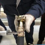
Bus air conditioner fan motor is a core component for efficient heat dissipation in air conditioning systems, and its performance directly determines system pressure, cooling efficiency, and operational reliability.
A study published in the 2025 issue of the quarterly journal *Commercial Vehicle Thermal Management Technology*, titled “The Critical Impact of Accessory Motor Failure on the Thermal Balance of Bus Air Conditioning,” points out that “a 30% decrease in condenser fan efficiency will lead to an approximately 18% increase in system operating high pressure, a 22% increase in compressor power consumption, and increase the risk of overheat protection triggering to more than three times the normal value.” This article focuses on the exhaust fan motor, breaking down its common faults into four dimensions: mechanical faults of the motor itself, electrical drive system faults, thermal management and environmental load, and systemic maintenance strategies. Following a logic from component to system, from diagnosis to prevention, it provides structured solutions.
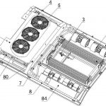
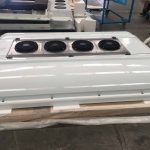
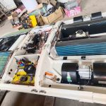
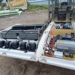
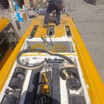
Content Module 1: Bus Air Conditioner Fan Motor—Physical Failures of Bearings, Impellers, and Structures
Current Problem:
The motor produces abnormal noises (humming, creaking), increased vibration, or the impeller may become stuck or completely seized, resulting in a significant decrease in airflow or no airflow at all. This is the most obvious manifestation of mechanical failure.
Problem Analysis: The root cause of this type of failure lies within the motor or related mechanical components:
1. Bearing Wear and Lubrication Failure: Long-term high-load operation, water ingress, or dust intrusion leads to dried-out bearing grease and ball wear, resulting in abnormal noise and increased rotational resistance, eventually causing seizure.
2. Impeller (Fan Blade) Damage or Deformation: External impact, improper installation, or material fatigue can cause impeller blades to break, deform, or rub against the fan ring, disrupting dynamic balance, affecting airflow, and exacerbating vibration.
3. Motor Shaft Bending or Loose Mounting Bracket: Loose mounting bolts or continuous vibration during vehicle operation may cause slight bending of the motor shaft or deformation of the mounting base, leading to misalignment.
Solutions:
1. Diagnosis and Replacement: Manually rotate the impeller to check for jamming, abnormal noise, or axial/radial play. If the bearing is damaged, the entire motor assembly (most are sealed designs) usually needs to be replaced. 2. Impeller Inspection and Replacement: Visually inspect the impeller for integrity. Replace any deformed or damaged impellers, ensuring the new impeller fits tightly to the motor shaft without any wobble after installation.
3. Reinforcement and Alignment: Tighten all mounting bolts and check the bracket for cracks. For high-end models or suspected shaft bending, a simple radial runout test can be performed.
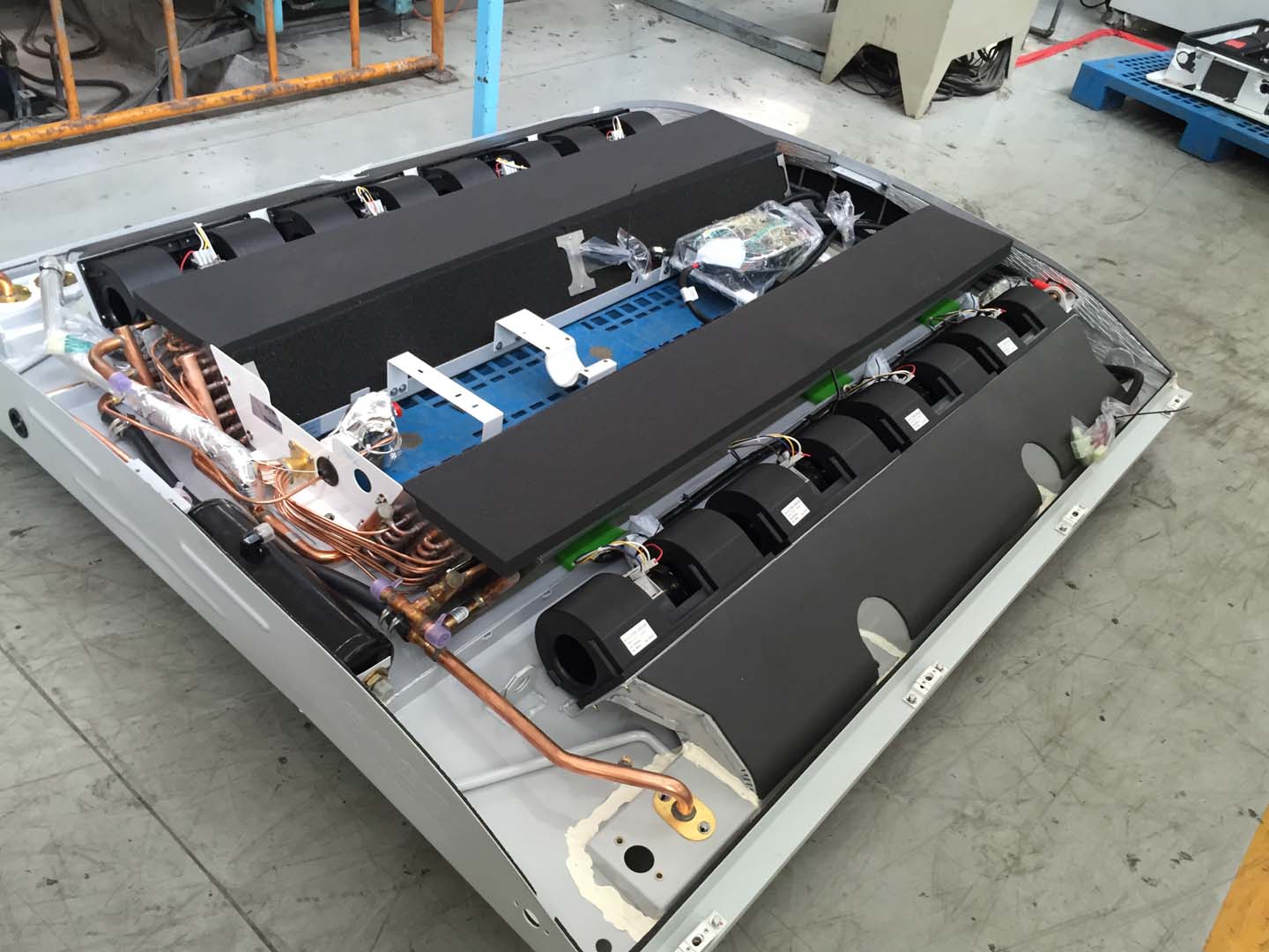
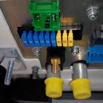
Content Block Two: Bus Air Conditioner Fan Motor Electrical Drive System Failure – Interruption of the Signal Chain from Power Supply to Control
Current Problem:
The motor cannot start at all, or can only operate at a single fixed speed (unable to switch between low and high speeds), but the mechanical rotating parts are normal.
Problem Analysis: The fault lies in the electrical circuit that provides power and commands to the motor:
1. Power Circuit Failure: Blown fuse, burnt relay contacts or failed coil, open circuit, or corroded connectors, preventing power from reaching the motor.
2. Damaged Motor Windings: Use a multimeter to measure the resistance of the motor windings. If the resistance is infinite (open circuit) or far below the standard value (inter-turn short circuit), the internal coils of the motor are damaged.
3. Speed Control Failure: For multi-speed motors, a burnt-out speed control resistor module or a faulty electronic speed controller (PWM module) can cause the fan to be unable to change speed. A malfunctioning temperature sensor signal (such as a condenser temperature sensor) can cause the control unit (ECU) to issue incorrect fan commands.
Solutions:
1. Circuit Troubleshooting: Follow the sequence of “fuse → relay → wiring/plug → motor,” using a multimeter to measure the power supply voltage and grounding to confirm circuit continuity.
2. Component Testing and Replacement: Measure the resistance of the motor windings to determine their condition. Check the speed control resistor for burn marks, or use a diagnostic tool to read the ECU’s fan control duty cycle commands to determine if the problem lies with the controller or actuator.
3. Data Stream Diagnosis: Use a diagnostic tool to read the data stream from relevant temperature sensors and compare it with the actual temperature to rule out control logic problems caused by erroneous signals.
Content Block 3: Thermal Management and Environmental Load – Performance Degradation and Overload Due to Extreme Operating Conditions
Problem Status:
Under high-load conditions such as high temperatures, prolonged idling, or hill climbing, the fan suddenly stops after continuous high-speed operation, or the system frequently shuts down due to high-voltage protection.
Problem Analysis: This fault stems from the motor operating under prolonged overload conditions in extreme environments:
1. Thermal Overload: A dirty or clogged condenser, excessive refrigerant, or air entering the system cause a surge in heat dissipation load, forcing the fan motor to operate at maximum power output for extended periods. This excessive internal temperature rise may trigger the built-in thermal protection switch or accelerate insulation aging.
2. Environmental Corrosion and Blockage: The fan motor is located behind the condenser at the front of the vehicle and is exposed to moisture, salt (in coastal areas), and dust and pollen for extended periods, which may corrode the motor housing, seals, and even block the motor’s own heat dissipation vents.
3. Unstable Voltage: Excessive voltage fluctuations in the vehicle’s electrical system (such as a faulty alternator regulator) cause abnormal motor operating current, affecting its lifespan.
Solutions:
1. Reduce System Load: The fundamental measure is to thoroughly clean the condenser, ensure accurate refrigerant metering and adequate system vacuum, reducing the fan’s heat dissipation pressure at the source.
2. Improve Working Environment and Inspection: Regularly clean debris around the fan motor and check for unobstructed ventilation holes. For vehicles operating in corrosive environments, consider waterproofing and corrosion-resistant treatment of the motor connectors.
3. System Voltage Monitoring: Measure the voltage across the battery terminals when the fan is operating, ensuring it is within the normal range (typically 26-28V for a 24V system) to prevent abnormal motor performance or damage due to voltage issues.
Content Block Four: Systemic Maintenance Strategy – Predictive Maintenance and Assembly Optimization
Current Problem:
The lack of regular inspection and preventative replacement strategies for exhaust fan motors leads to reactive maintenance after failures occur, impacting operations and potentially causing secondary system damage (such as compressor high-pressure damage).
Problem Analysis:
Fan motors are typical “wear parts,” with their lifespan strongly dependent on the working environment and load. Reactive maintenance is costly and risky.
Solutions:
1. Establish a preventative inspection system: During the seasonal maintenance before each summer, make fan motor functional testing a mandatory item. The test should include: auditory inspection (for abnormal noises), speed measurement (to ensure normal high and low speeds), and current measurement (to check for abnormalities compared to rated values).
2. Assembly replacement and upgrade recommendations: When replacing components, it is strongly recommended to replace the fan motor and impeller as an assembly to ensure dynamic balance and performance matching. For models with frequent malfunctions, research upgrade parts with superior heat dissipation performance and higher protection ratings (IP rating) on the market.
3. Integrated system monitoring: For fleets equipped with intelligent systems, high-voltage data of the air conditioning system can be monitored through a remote monitoring platform. If a trend of increasing high-voltage values is detected under the same operating conditions, an early warning can be issued, and the fan cooling efficiency can be checked, enabling predictive maintenance.
Bus air conditioner fan motor summary
The stable operation of the bus air conditioning exhaust fan motor is the cornerstone of maintaining the thermal balance of the entire refrigeration system. Troubleshooting its malfunctions requires a holistic approach encompassing “mechanical-electrical-environmental-system.” The core maintenance logic is: first, manually check the mechanical condition and circuit continuity; then, use tools for data-driven diagnosis (resistance, current, data flow); subsequently, eliminate the root cause of overload at the system level (such as a clogged condenser); and finally, prevent recurrence of faults by establishing a preventative maintenance system. Only by treating the exhaust fan motor as a key active component in a dynamic system, rather than an independent rotating electrical appliance, can its faults be fundamentally addressed, ensuring the long-lasting, efficient, and quiet operation of the bus air conditioning system in various harsh environments.
Related posts:
 Bus AC not blowing air
 Bus AC fan not working
 Bus Air Conditioner is used for buses and medium-sized commercial vehicles
 Acc Bus Air Conditioning
 Bus AC Fuse Blown Analysis and Root Cause Solution
 Analysis and Solutions to Bus AC Pressure Problems
 Introduction to Ac For Bus
 Diagnosis and Systematic Solutions for Bus AC Leaking Water
 Bus Aircon Issues and Solutions
 Bus Air Conditioner Repair Manual