Bus Air Conditioner Refrigerant Design is the core of overall vehicle thermal comfort and the “general outline” of air conditioning system design.
Cooling capacity is not an isolated technical indicator, but a comprehensive systems engineering project encompassing theoretical calculations, regional matching, system verification, and regulatory compliance.
Bus Air Conditioner Refrigerant Design – Theoretical Calculation Dimension: Precise Solution of Load Composition
The starting point for cooling capacity design is the precise calculation of the vehicle’s heat load. The heat load inside a bus mainly comes from five aspects: solar radiation heat and temperature difference heat transfer through the walls and windows; fresh air heat seeping into the vehicle through gaps; sensible and latent heat dissipated by the human body; heat transferred from the engine compartment (or motor and electronic control system) through the walls; and heat released by components inside the vehicle. Traditional empirical estimation methods (such as estimating at 400 kcal/h per passenger) are no longer sufficient to meet the comfort and economy requirements of modern buses. Therefore, the design must adopt a steady-state heat transfer method to calculate each of the above loads individually and sum them to obtain the theoretical heat load of the vehicle body. To address the issues of cumbersome manual calculation formulas and complex parameters, modern design has begun to utilize computer programs based on VB or similar platforms for assisted calculations. These programs can quickly and accurately solve for theoretical heat loads, providing a theoretical basis for determining cooling capacity.
Bus Air Conditioner Refrigerant Design – Precise Regional Dimensions, Addressing Uneven Load Distribution Within the Carriage
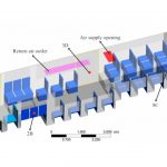
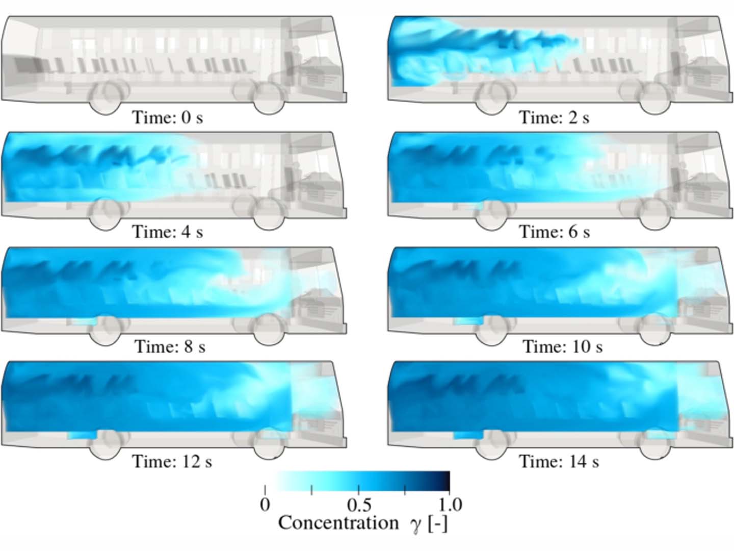
Comprehensive design must consider the uneven distribution of heat load within the carriage. Due to factors such as the angle of sunlight, passenger density, and engine location, the heat load in the front, middle, and rear of the carriage often differs significantly. Therefore, the total cooling capacity cannot be the sole objective; instead, the carriage should be divided into several zones (such as a five-zone model), and the heat load of each zone should be calculated separately. Based on the theoretical airflow requirements of each zone, the number, location, and airflow area of air outlets are determined. This refined design based on regional heat loads effectively avoids the uneven temperature field phenomenon of “one area cold, one area hot” found in traditional designs, ensuring the comfort of the entire carriage.
Bus Air Conditioner Refrigerant Design – System Matching Dimensions: Coupling of Cooling Capacity and Duct Resistance
Cooling capacity design is not simply a matter of “choosing a number”; it must be coupled and matched with the duct system. After selecting the air conditioning unit, duct design is required based on the theoretical airflow: initially determine the main duct airflow velocity, calculate the main duct cross-sectional area, and determine the cross-sectional shape in conjunction with the vehicle’s interior trim requirements. Then, the total resistance of the air supply duct system must be calculated (including duct friction resistance, local resistance, return air inlet resistance, etc.), and this resistance must be compared and verified against the evaporator fan’s performance curve. If the total system resistance is greater than the fan’s outlet pressure, the fan’s actual operating point will shift, resulting in an actual airflow lower than the theoretical requirement, ultimately manifesting as “insufficient cooling capacity.” In this case, the duct cross-sectional dimensions need to be adjusted to reduce resistance, or a fan with a higher outlet pressure needs to be selected to ensure that the cooling capacity can be effectively delivered.
Bus Air Conditioner Refrigerant Design – New Energy Dimension: Integrated Considerations for Battery Thermal Management
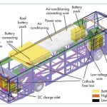
For pure electric buses, cooling capacity design has expanded from a single aspect of “passenger compartment environment control” to an integral part of the overall vehicle thermal management system. The battery packs of electric buses generate significant heat during charging and discharging, affecting battery life and even potentially triggering thermal runaway. The air conditioning system is often used to cool the batteries. Therefore, cooling capacity design must consider the additional load of battery cooling: when the Bus Air Conditioner simultaneously cools the passenger compartment and the battery pack, the cooling capacity requirement increases significantly. The design must clearly define whether the air conditioning system has dual evaporators or a multi-flow path mode to simultaneously meet the needs of passenger compartment air conditioning and battery cooling. This dimension closely links cooling capacity design with the overall vehicle safety and range.
Bus Air Conditioner Refrigerant Design – Special Operating Condition Dimension: Altitude and Environmental Adaptability
Cooling capacity design also needs to cover performance corrections under special operating conditions. For air-conditioned buses used in high-altitude areas, the reduced atmospheric pressure leads to decreased air density and reduced heat exchange efficiency, thus affecting the actual cooling capacity of the air conditioning unit. The design must consider performance conversion under different air pressure conditions. The required cooling capacity should be calculated based on the enthalpy and moisture content of the air, rather than simply applying selection parameters from plains areas. Similarly, for high-temperature and high-altitude regions, design redundancy or variable frequency technology should be added to the standard operating conditions for adjustment.
Bus Air Conditioner Refrigerant Design – Regulatory and Verification Dimensions: Standard Compliance
The final determined cooling capacity must comply with national and industry standards. According to China’s “Technical Conditions for Bus Air Conditioning Systems” (JT/T 216-2020), the cooling performance of the air conditioning system must be verified in an enthalpy difference laboratory or under vehicle conditions according to the prescribed test methods, and the test results must meet the performance classification requirements in the standard. In addition, the design must also meet relevant standards such as GB/T 21361 “Automotive Air Conditioners” to ensure the authenticity and reliability of the nominal cooling capacity.
Bus Air Conditioner Refrigerant Design is a comprehensive system engineering project that starts with theoretical calculations of heat load, proceeds through precise regional allocation, coupling of air duct systems, integration of new energy functions, correction for special operating conditions, and finally concludes with regulatory verification.