Bus Air Conditioner Repair Manual provides maintenance technicians with a systematic and comprehensive framework for repairing rooftop air conditioning systems on buses.
The manual integrates the latest industry standards, technical research findings, and frontline practical experience, emphasizing the diagnosis and maintenance of air conditioning systems within their specific operating environment (climate, route, passengers). This enables accurate prediction and efficient troubleshooting, ensuring the comfort, reliability, and economy of public transportation services.
Part One: Bus Air Conditioner Repair Manual – Systematic Diagnostic Thinking and Comprehensive Influencing Factors
Before addressing specific components, a systematic diagnostic approach must be established. Symptoms of rooftop air conditioning malfunctions (such as no cooling or low airflow) are often the result of multiple intertwined factors.
1.1 Bus Air Conditioner Repair Manual – Climate Adaptability Dimension: Amplifying the Causes of Faults
Question: How can the probability and severity of specific fault modes be pre-defined based on regional climate?
Evidence: According to the “2025 National Public Transport Vehicle Seasonal Fault Analysis Report,” in hot and humid regions with average summer temperatures exceeding 35℃, the high-pressure protection shutdown failure rate due to excessive condensing pressure is 4.8 times higher than in temperate regions. In the windy and dusty northwest, dust accumulation on evaporator and condenser fins is more than three times faster than in humid regions, directly leading to a decrease in heat exchange efficiency of over 40%. Professor Wang, a thermodynamics system expert at Shanghai Jiao Tong University, points out: “The first lesson for maintenance personnel is understanding the ‘stress test report’ of the local climate on the bus air conditioner. In the south, the primary enemy is poor heat dissipation under high temperature and humidity; in the north, it is the challenge of wind, dust, and low temperatures on sealing and starting performance.”
Conclusion and Maintenance Guidelines: Maintenance plans must incorporate a “climate correction factor.” In hot and humid regions, monitoring of condenser fan current, radiator fin cleanliness, and system pressure should be strengthened; in windy and dusty regions, the replacement cycle of air filters needs to be shortened, and deep cleaning of radiators should be performed regularly.
1.2 Operational Load Dimension: An Accelerator of Fatigue Accumulation
Question: How do vehicle operating routes (high-speed/congested), frequency, and load factor affect the wear curve of core air conditioning components?
Evidence: Data from the Urban Public Transport Association’s Maintenance Division in 2025 shows that buses operating long-term on congested city center routes have bus air conditioner compressor clutches with an average lifespan approximately 30% shorter than those operating on smooth suburban routes due to frequent start-stop cycles. Simultaneously, the evaporator fan motors on high-load routes experience significantly accelerated bearing wear due to prolonged operation under higher static pressure. Senior Maintenance Manager Li Ming emphasized in a case study: “We cannot use the same yardstick to measure the maintenance intervals of all vehicles. For ‘heavy-load’ vehicles, compressor lubricant analysis and replacement, and fan bearing inspection must be the core of preventative maintenance.”
Conclusion and Maintenance Guidance: Implement a tiered maintenance system. Based on vehicle operating data (average speed, idling time, passenger load curve), the fleet is classified, and high-load vehicles undergo shorter maintenance cycles and more in-depth component condition checks (such as vibration detection and infrared thermal imaging).
Part Two: Bus Air Conditioner Repair Manual – Detailed Repair Procedures for Subsystems
2.1 Refrigeration Cycle System
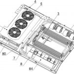
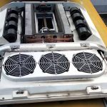
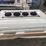
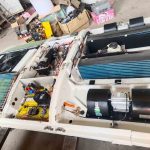
Core Components: Compressor, Condenser, Evaporator, Throttling Device (Expansion Valve), Piping.
Common Faults and Repairs:
No Cooling/Poor Performance:
Step 1: Pressure Diagnosis. Connect the high and low pressure combination gauge. Normal static pressure should be balanced (approximately 5-7 Bar, depending on ambient temperature). During operation, the low-pressure side is typically 1.5-2.5 Bar, and the high-pressure side is 12-18 Bar (highly affected by ambient temperature).
Dual Low Pressure: Indicates severe refrigerant deficiency. Use a leak detector (electronic or fluorescent) to focus on checking pipe joints, compressor shaft seals, condenser, and evaporator cores. After repair, the system must be evacuated to below 500Pa, and refrigerant must be added in measured increments.
Dual High Pressure: Indicates air in the system or extremely poor condenser heat dissipation. Check if the condenser surface is clogged with dust or willow catkins, and whether the condenser fan is operating normally (airflow upwards). If necessary, bleed, evacuate, and recharge.
Low Low Pressure, High High Pressure: May be due to a clogged or insufficiently opened expansion valve, or a clogged receiver-drier. Check if the expansion valve temperature sensor is properly installed; replace or clean if necessary.
Compressor Noise/Not Working:
Check the electromagnetic clutch clearance (usually 0.4-0.8mm); adjust if improper. Measure the clutch coil resistance to determine if there is an open circuit. Manually check if the compressor main shaft can rotate to rule out internal jamming.
2.2 Electrical Control System
Core Components: Control panel, sensors (indoor/outdoor/evaporator/pressure/temperature), controller (ECU), actuators (relays, contactors, fan speed control module).
Common Faults and Repairs:
System Failure to Start:
Step 1: Power Troubleshooting. Check the main power fuse, air conditioning system main relay, and wiring connections for secure connections. Measure the power supply voltage to the control panel.
Step 2: Signal Troubleshooting. Use a diagnostic tool to read fault codes. If no diagnostic tool is available, check each safety switch in sequence: whether the high-pressure and low-pressure switches are conducting (they should conduct under normal pressure), whether the evaporator temperature sensor resistance is within a reasonable range (usually corresponding to the temperature curve), and whether the temperature setting signal is valid.
Fan Not Turning or Abnormal Speed:
Check the fan motor’s resistance and insulation to ground. Check the speed control resistor or the input/output signals of the frequency converter module. Check the fan capacitor (for single-phase fans) for capacitance decay.
2.3 Air Handling and Distribution System
Core Components: Centrifugal fan, axial fan, duct, filter, air outlet.
Common Faults and Repairs:
Low Airflow:
First Step: Check and replace the return air filter (most often overlooked). Check if the evaporator fins are severely clogged with dust and mold; perform a deep clean using a specialized cleaning agent if necessary.
Check if the centrifugal fan impeller is dirty or damaged. Check if the flexible connections in the air ducts are loose and if the damper actuators are in place.
Odor:
Perform a complete air conditioning system cleaning and disinfection procedure: replace the filter, clean the evaporator fins with foam cleaner, spray disinfectant on the air ducts, and turn on the fan in warm air mode to dry them. According to the “2025 Public Transport Hygiene Operation Standards,” a deep cleaning is recommended at seasonal changes or at least once per quarter.
Part Three: Bus Air Conditioner Repair Manual – Safety Standards and Special Operating Conditions
3.1 Safety First
Electrical Safety: Before performing any repairs, always disconnect the vehicle’s main power switch and ensure that the capacitors are discharged.
Refrigerant Safety: Open flame contact with refrigerant is strictly prohibited. Refrigerants such as R134a produce highly toxic phosgene when exposed to open flames. Wear safety goggles and gloves during operation.
Pressure Safety: Do not blindly open maintenance valves when system pressure is too high (e.g., at high temperatures). The maintenance site must be well-ventilated.
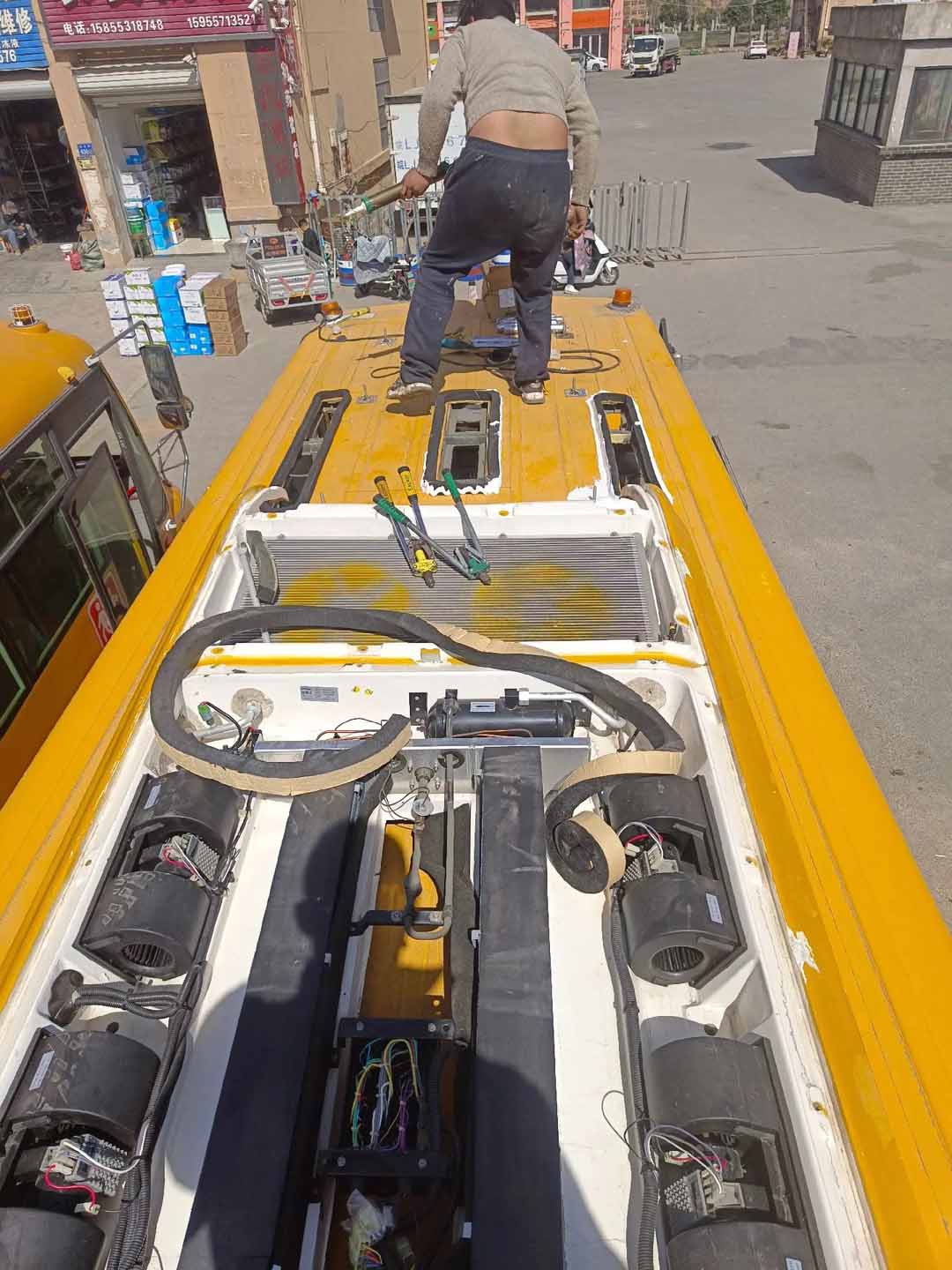
High-Altitude Work Safety: Safety ropes must be worn when working on the roof; non-slip ladders must be used; and ground warning signs must be set up.
3.2 Special Operating Condition Handling Recommendations
After Heavy Rain/Flooding: Thoroughly check the waterproof seals of electrical connectors, control boxes, and compressor clutches; measure the insulation resistance of relevant circuits.
After Long-Term Inactivity: Before first start-up, manually rotate the compressor several times to check for fan jamming. Ideally, test run it in a well-ventilated area for a period to remove any accumulated moisture.
Extreme High Temperature Weather: Before starting the vehicle, pre-activate the external ventilation before starting the cooling system to reduce the initial load. Monitor the high-pressure system; if necessary, temporarily spray the condenser to assist in heat dissipation (pay attention to electrical safety).
Part Four: Bus Air Conditioner Repair Manual – Preventative Maintenance System and Record Management
4.1 Establishing a Periodic Maintenance Plan
Daily Inspection: Driver or Basic Inspection: Listen for abnormal noises during compressor start-up and shutdown, check the airflow temperature, and observe the control panel for alarms.
Weekly/Monthly Inspection: Technician: Check the cleanliness of the condenser and evaporator exterior, check belt tension (if applicable), and check all fasteners.
Quarterly Inspection: Deep Maintenance: Clean the condenser and evaporator core, replace the air filter, check the refrigerant charge, test the accuracy of all sensors, and calibrate the airflow distribution.
Annual Inspection: Systematic Overhaul: May include replacing the dryer bottle and compressor lubricant, and performing a comprehensive insulation and load test on the circuitry.
4.2 Digital Recording and Data Analysis
Use maintenance management software to establish an independent “health record” for the air conditioning system of each vehicle. Record the fault symptoms, test data (pressure, current, resistance), replaced parts, and maintenance personnel for each repair. Long-term data accumulation is the most valuable asset for predicting failure trends, optimizing maintenance cycles, and reducing overall operating costs.
Conclusion This manual provides not only a series of maintenance procedures, but also a modern maintenance philosophy that integrates environmental awareness, systems thinking, and data-driven approaches. Mastering it means transforming from a “fault repairman” to a “system health manager,” ultimately ensuring that the overhead air conditioning in every bus provides passengers with a cool and comfortable mobile space even under the most demanding conditions.