Bus Air Conditioning Airflow Diagnosis and Optimization
Bus air conditioning airflow is the carrier of heat exchange and distribution; its organizational efficiency directly determines temperature control accuracy, comfort, and energy consumption. Poor airflow distribution is a major cause of passenger complaints about “stuffy heat, direct cold airflow, and odor diffusion.” According to data from the article “Research on the Correlation between Airflow Organization and Comfort in Bus Cabins” published in *Bus Technology and Research*, 2025, approximately 40% of passenger subjective discomfort can be attributed to airflow organization design or operational malfunctions. Airflow issues are a comprehensive subject involving aerodynamics, mechanical structure, and control, requiring system-level analysis.

Sub-problem 1: Bus Air Conditioning Airflow – Ventilation Path
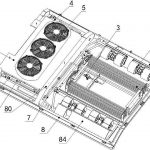
Current Status: Bus air conditioning ducts (especially concealed flexible ducts) suffer from aging and deformation, internal insulation layer detachment, or accidental compression, resulting in a reduced effective cross-sectional area and abnormally increased air resistance. Simultaneously, aging and cracking of the sealant at duct connections causes air leakage, leading to a loss of rated airflow to the target area, resulting in “loud airflow” at the front and “low airflow” at the rear.
Problem Analysis: Professor Chen Ming of the Institute of Refrigeration and Cryogenic Engineering at Shanghai Jiao Tong University pointed out at the 2025 International Automotive Air Conditioning Symposium (IMAC): “The airtightness and flow resistance characteristics of the duct system are easily overlooked after vehicle assembly, yet they are fundamental to the uniformity of airflow distribution. Our experiments have found that due to installation stress or material fatigue, the flow resistance of some ducts can increase by more than 30% after several years of vehicle operation, directly leading to increased blower load, increased noise, and decreased air delivery efficiency.” Leaks can further disrupt the pre-designed airflow organization, causing hot and cold air to mix and be lost in non-target areas such as the ceiling cavity.
Conclusion: Ducts are the “highways” of airflow, and their unobstructed flow and airtightness are fundamental requirements. The conclusion is that regular maintenance should include increased testing of the flow resistance and airtightness of key duct sections, priority should be given to using rigid or high-stability composite material ducts, and long-term sealing processes should be implemented at the joints.
Sub-problem 2: Bus air conditioning airflow – Air distribution
Current situation: The air vent louver adjustment mechanism (manual or electric) is stuck or damaged, preventing airflow direction adjustment and causing cold air to blow directly onto passengers. Simultaneously, the existing vent layout fails to differentiate for the varying heat loads of different seating areas (e.g., front and rear rows, left and right sides, upper and lower decks), resulting in uneven overall airflow distribution.
Problem analysis: Liu Tao, chief layout engineer of a leading domestic bus manufacturer, analyzed in the “White Paper on Bus Ergonomics Optimization” published in 2025: “The vent layout is the ‘last mile’ of airflow distribution. Traditional symmetrical layouts ignore the asymmetry of actual solar radiation and changes in passenger density. For example, the right side, which experiences severe sunset radiation, should have stronger airflow capacity or higher vent density. Furthermore, manual vents have a high failure rate, while electric damper actuators face cost and reliability challenges.”
Conclusion: Air distribution needs a shift in thinking from “uniform sprinkling” to “precise drip irrigation.” The conclusion is that future air vent designs should be based on passenger cabin heat load simulation for asymmetrical, zoned layouts, and highly reliable, low-cost electric airflow/direction/volume adjustment mechanisms should be developed to achieve dynamic, personalized airflow distribution.
Sub-problem 3: Bus air conditioning airflow
Current situation: The return air filter has not been replaced for a long time and is severely clogged, causing a sharp drop in total circulating airflow, resulting in the air conditioner only cooling without airflow. Dust and mold accumulation on the evaporator fins form insulation and air resistance layers, severely weakening heat exchange efficiency and potentially becoming a breeding ground for odors and bacteria.
Problem analysis: This is the most common cause of reduced airflow and decreased air quality. A special report in the April 2025 issue of *Commercial Vehicle Maintenance and Repair* quoted senior vehicle maintenance expert Zhao Hong as saying: “In dusty operating environments, ordinary filters may reach their clogging limit within a quarter. Many users only focus on ‘whether it’s cold enough,’ neglecting ‘whether the airflow is sufficient.’ More seriously, biological contamination on the damp evaporator can spread with the airflow, causing complaints of ‘air conditioning sickness,’ which is already a public health issue.”
Conclusion: The air handling unit is the “gatekeeper” of airflow and air quality. The conclusion is that a strict, mandatory periodic filter replacement system must be implemented (with shorter cycles depending on the environment), and an automatic evaporator cleaning or periodic professional deep cleaning process should be introduced to ensure airflow cleanliness from the source.
Sub-problem 4: Bus air conditioning airflow – Power drive
Current situation: The blower motor’s speed has decreased and noise has increased due to carbon brush wear (brushed motors) and bearing lubrication failure; dirt accumulation on the blower impeller has disrupted its dynamic balance. A malfunction in its speed control module (resistive or PWM module) causes the airflow to be unable to be adjusted, often remaining at a fixed high or low setting.
Problem Analysis: A misaligned power source will render all front-end optimizations ineffective. At the 2025 Asian Bus Exhibition Technical Forum, the technical director of a well-known German thermal management system supplier stated, “The long-term reliability of the blower assembly is crucial. We are promoting brushless DC motors, which have a longer lifespan and more precise controllability. Simultaneously, airflow control strategies should be deeply coupled with temperature control, rather than operating independently. Currently, many systems only reduce compressor power after reaching the set temperature, without correspondingly reducing airflow, resulting in excessively cold outlet air and energy waste.”
Conclusion: The blower is the “heart” of the airflow system, and intelligent control is the trend. The conclusion is to promote the adoption of highly reliable brushless motors and intelligent speed control strategies, enabling airflow to dynamically and smoothly adjust with heat load, achieving the optimal balance between cooling efficiency and comfort.
Bus Air Conditioning Airflow – Summary
Bus air conditioning airflow issues are a complete system engineering problem, from “source power” to “terminal distribution,” then to “path assurance” and “quality handling.” A failure in any single link will lead to a collapse in overall performance. The future direction of optimization will inevitably be the integration of “low-resistance sealed air ducts, precisely adjustable air outlets, clean and efficient heat exchange, and intelligent collaborative drive.” As Professor Chen Ming emphasized, “The ideal airflow organization should be like a silent spring breeze, evenly and gently filling the entire space, carrying away heat and stale air without passengers noticing its presence. This is the ultimate goal of comfort design.” This requires the industry to carry out comprehensive and refined upgrades from design, materials, control to maintenance.
Related posts:
 Bus Air Conditioner is used for buses and medium-sized commercial vehicles
 Bus AC not blowing air
 Acc Bus Air Conditioning
 Air Conditioner In Camper
 Introduction to Ac For Bus
 Bus AC Temperature Control Diagnosis and Optimization Analysis
 Bus Air Conditioner Troubleshooting: A Systematic Diagnosis from Climate Adaptability to Passenger Experience
 Diagnosis and Systematic Solutions for Bus AC Leaking Water
 Bus Air Conditioning Sensor Classification and Repair
 Bus air conditioner not turning on: In-depth diagnostic logic
 IC Bus Air Conditioning: A Comprehensive Evolution of Integration, Intelligence, and Sustainability
 Bus Air Conditioning Unit
 Diagnosis and Repair of Bus AC Electrical Issues
 Bus Con Supplier reminds all bus owners to clean BUS AC
 Van Air Conditioner
 Bus AC fan not working
 Bus air conditioner diagnostic
 Air Conditioner for Bus Conversion