Bus AC pressure problems are a clear manifestation of a fault, but not the root cause itself. Pressure is the “blood pressure” of the refrigeration system; its high and low pressure readings directly reflect the overall state of energy flow and heat exchange within the system.
A special paper published in the 2025 *International Automotive Air Conditioning Technology Yearbook*, titled “Research on the Dynamic Relationship between Pressure Dynamics and Fault Mapping in Commercial Vehicle Refrigeration Systems,” pointed out through big data analysis that over 70% of pressure anomaly cases have root causes outside the components indicated by the pressure readings, resulting from system-wide collaborative failures.
Professor Zhang Zhengming, Chief Scientist of Thermal Management at the National Engineering Laboratory, emphasized: “Interpreting pressure requires moving from static readings to dynamic balance analysis. Each combination of high and low pressure corresponds to a unique system ‘energy narrative.'”
This article avoids the misconception of simply adjusting pressure; instead, it delves into four interrelated systemic dimensions, each following the logic of “problem status – problem analysis – problem conclusion,” constructing a diagnostic tree for accurately locating the root cause.
Dimension One: Bus AC Pressure Problems – Imbalance in Pressure Generation and Regulation
Problem Status: Static pressure is normal, but during operation, both the high-pressure and low-pressure sides deviate abnormally from the standard range. Common combinations include: both high and low pressures are too high; both high and low pressures are too low; or the high pressure is abnormally high while the low pressure is abnormally low (or vice versa).
Problem Analysis: This dimension focuses on the “pumps” and “valve” of the refrigerant cycle. Pressure is the result of the combined effect of the compressor’s work and the resistance of the throttling element.
1) Both high and low pressures are too high: This usually indicates extremely poor system heat dissipation (complete condenser blockage, fan stoppage) or severely excessive refrigerant charge, preventing the system from effectively dissipating heat and storing excess refrigerant.
2) Both high and low pressures are too low: This primarily indicates insufficient refrigerant charge (leakage), resulting in insufficient system circulation flow.
3) High pressure too high, low pressure too low: This typically manifests as blockage on the high-pressure side of the system, such as a blocked receiver-drier, flattened pipes, or a malfunctioning expansion valve sensor causing insufficient opening, creating a “blocked front, empty back” situation. Professor Zhang Zhengming points out: “When observing both high and low pressure simultaneously, the first step is to determine whether the problem lies in ‘flow rate’ or ‘resistance.'”
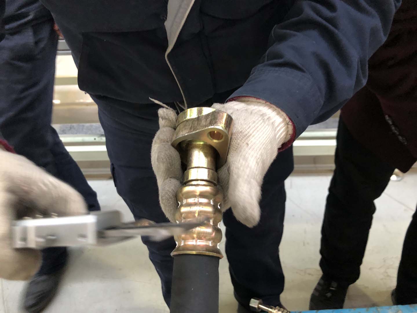
Diagnostic Conclusion: Initially pinpointing the fault direction through the “high and low pressure combination mode” is the primary step in diagnosis. Conclusion Requirements: Connect high and low pressure gauges and read stable pressures under standard operating conditions (e.g., ambient temperature 30℃, engine 2000rpm, maximum internal circulation airflow). Comparing the measured combination with the standard combination can quickly direct the investigation focus to the cooling system, refrigerant charge, or circulation blockage. This is the logical starting point for systematic diagnosis.
Dimension Two: Bus AC pressure problems – Heat exchange efficiency mismatch – efficiency degradation on the condenser and evaporator sides
Current Problem: Abnormal pressure is usually accompanied by synchronous temperature abnormalities. For example, high pressure and abnormally high condenser outlet (receiver dryer) temperature; low pressure and frost formation on the evaporator surface or excessively small inlet and outlet temperature difference.
Problem Analysis: Pressure problems are essentially an external manifestation of heat exchange problems. Pressure and temperature are closely coupled (approximately saturated) in the refrigeration cycle.
1) Abnormally high pressure accompanied by high temperature: This directly indicates insufficient heat exchange in the condenser, preventing heat dissipation. Check for clogged condenser fins, insufficient fan speed, or poor airflow sealing.
2) Abnormally low pressure accompanied by low temperature (or frosting): This indicates insufficient heat absorption capacity of the evaporator or excessive throttling. This may be due to clogged evaporator fins, insufficient blower airflow, or excessively low air temperature entering the evaporator (damper control malfunction). The paper “Pressure Dynamics Research” points out that measuring the air temperature difference between the condenser and evaporator inlet and outlet sides is a more direct indicator of heat exchange efficiency than simply looking at the pressure.
Diagnostic Conclusion: Pressure readings must be cross-validated with key temperature measurements to distinguish between “true” and “false” pressure faults. Conclusion Requirements: During diagnosis, while reading the pressure, an infrared thermometer must be used to measure: the surface temperature of the condenser’s middle section, the condenser outlet pipe temperature, the evaporator surface temperature, and the temperature difference between the inlet and outlet of the expansion valve. The temperature field distribution clearly indicates whether poor heat dissipation or poor heat absorption is causing the pressure imbalance.
Dimension 3: Bus AC Pressure Problems – Electrical Control and Sensor Malfunctions
Current Problem: Unstable, intermittent, or significantly inconsistent pressure readings with system performance (e.g., outlet air temperature). Diagnostic tools may show pressure sensor data drift, inconsistencies with other parameters, or related actuators (fan, compressor variable displacement valve) malfunctioning as expected.
Problem Analysis: In intelligent systems, pressure is not only a physical parameter but also an input signal for the control system. Faults may occur in the following ways:
1) Pressure sensor signal distortion: The sensor itself drifts, is damaged, or its power supply, grounding, or signal lines are interfered with, reporting incorrect pressure values to the control unit (ECU), leading to incorrect ECU decisions (e.g., shutting down the compressor due to a false high-pressure report).
2) Actuator response failure: Even if the ECU command is correct, condenser fan speed control malfunctions (constantly operating at low speed), or the compressor variable displacement control valve is stuck, failing to dynamically adjust according to the pressure signal, resulting in uncontrolled pressure.
3) Control logic defects: The software calibration sets pressure protection thresholds that are too sensitive, or the response logic is slow, causing the system to malfunction under normal fluctuations.
Diagnostic Conclusion: When abnormal pressure contradicts physical inspection results, the integrity of electrical signals and the correctness of control logic must be verified first. Conclusion Requirements: Use a diagnostic tool to read the real-time data stream from the pressure sensor and directly compare it with the reading of the mechanical pressure gauge to verify the sensor’s accuracy. Simultaneously, observe whether the target fan speed matches the actual speed, and whether the target compressor displacement matches the command. Utilize the actuator testing function to actively drive the fan and compressor and observe the pressure change response.
Dimension Four: Bus AC Pressure Problems – System Operating Conditions and External Environment Misalignment
Current Problem: Pressure problems only occur under specific conditions, such as: excessively high pressure only when the vehicle is traveling at high speed; excessively low pressure only when idling or at low speed; or persistently abnormal pressure after replacing new parts or changing the refrigerant brand.
Problem Analysis: Bus air conditioner is not an isolated system; its pressure is significantly affected by the overall vehicle operating conditions and maintenance operations.
1) Engine Load and Cooling Environment: Climbing hills and high temperatures cause a sharp increase in engine compartment temperature, directly affecting the condenser intake air temperature, leading to a general increase in high pressure.
2) Improper refrigerant or refrigeration oil: Using different types of refrigerants, mixing refrigerants, or adding incompatible/deteriorated refrigeration oil will alter the system’s thermal properties, causing an overall shift in pressure characteristics.
3) Maintenance-related issues: Incomplete vacuuming can lead to air (non-condensable gases) in the system, significantly increasing high-pressure side pressure; or replacing components (such as expansion valves or compressors) may use the correct model but have mismatched capacities.
Diagnostic Conclusion: Diagnosis must consider the vehicle’s overall operating condition and maintenance history. Pressure analysis must be placed within a specific “scenario.” Conclusion Requirements: Inquire about and reproduce the specific operating conditions under which the fault occurred (vehicle speed, ambient temperature, engine status). Verify recent maintenance records to confirm the compliance of the refrigerant and lubricant brands and models used. For systems suspected of containing air, a “temperature-pressure” consistency test can be performed: When the system is stable, measure the saturation pressure corresponding to the temperature at the center of the condenser and compare it with the measured high pressure. If the measured pressure is significantly higher, air is likely present.
Summary of Bus AC Pressure Problems
Bus air conditioning pressure problems are not isolated parameter faults; they are the final output signal resulting from the coupling effects of system energy circulation, heat exchange efficiency, intelligent control response, and the external environment. A scientific diagnostic approach is as follows: First, identify the macroscopic fault type of energy flow through high and low pressure combination modes; then, verify the specific efficiency of the heat exchange links through key point temperature measurements; next, use diagnostic tool data streams to check the fidelity of electrical control signals and the fidelity of actuators; finally, perform final calibration by placing the analysis within specific vehicle operating conditions and maintenance history scenarios. This four-step diagnostic framework of “physical-thermal-electrical-scenario” ensures that we can accurately locate the initial imbalance point in the system beneath the complex pressure symptoms, thereby achieving system repair from the root, rather than simply adjusting readings.
Related posts:
 Bus air conditioner diagnostic
 Bus air conditioner not turning on: In-depth diagnostic logic
 Bus Air Conditioner is used for buses and medium-sized commercial vehicles
 Diagnosis and Repair of Bus AC Electrical Issues
 Acc Bus Air Conditioning
 Bus AC compressor problems- Analysis and Countermeasures
 Bus AC not cooling – A Comprehensive Troubleshooting Guide
 Bus Air Conditioner Repair Manual
 Bus Air Conditioner Troubleshooting: A Systematic Diagnosis from Climate Adaptability to Passenger Experience
 Bus AC fan not working
 Diagnosis and Systematic Solutions for Bus AC Leaking Water
 Bus AC service manual