KAMAZ Bus Air Conditioner Assembly is a highly specialized task, involving multiple fields such as mechanics, electrical engineering, refrigeration, and sheet metal work. It must be performed by professionally trained and certified technicians.
Main Components of a KAMAZ Bus Air Conditioner
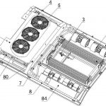
Before installation, let’s understand some of the core components of a bus air conditioning system:
Evaporator Assembly: Installed in the ceiling inside the passenger compartment, responsible for absorbing heat from the vehicle and blowing out cool air.
Condenser Assembly: Usually installed in the roof or rear of the vehicle, responsible for dissipating the heat generated by the refrigeration system to the outside.
Compressor: The “heart” of the air conditioning system, driven by the engine via a belt, compressing the refrigerant.
Pipeline System: Copper or aluminum pipes connecting the compressor, condenser, and evaporator, used for refrigerant circulation.
Control System: Includes control panel, sensors, wiring harnesses, etc., used to adjust temperature and fan speed.
KAMAZ Bus Air Conditioner
Step 1: Preparation and Planning
Based on the vehicle model and air conditioning unit model, accurately mark the opening locations and mounting points for the evaporator/condenser unit on the roof. It is essential to avoid the load-bearing beams of the roof.
Prepare specialized tools including an electric drill, riveting gun, screwdriver, multimeter, sheet metal cutting tools, welding torch, vacuum pump, and refrigerant recovery and charging machine.
Step 2: Roof Hole Cutting and Equipment Securing
At the marked locations, cut openings for the air supply and return vents according to the size of the evaporator chassis.
The edges of the openings need to be rust-proofed and sealed to prevent leaks and corrosion.
Use hoisting equipment to smoothly place the air conditioning unit (evaporator + condenser combination) on the roof, aligning it with the openings.
Use high-strength rivets or bolts to firmly secure the unit to the roof frame, ensuring it won’t loosen while driving.
Step 3: Compressor Installation and Belt Tensioning
Show the compressor mounting bracket location in the engine compartment. A dedicated bracket and pulley are usually required.
Secure the compressor to the engine and connect it to the engine crankshaft pulley via a belt.
Step 4: Piping Connections and Wiring
The connection path from the compressor to the condenser, and then to the evaporator’s intake and exhaust pipes.
Piping needs to be securely fixed to avoid friction with other vehicle components and with appropriate buffer bends.
Wiring harness connections between the control panel, speed control resistor, electromagnetic clutch, temperature sensor, etc.
Step 5: Vacuuming and Refrigerant Charging
Connect the blue (low pressure) and red (high pressure) hoses of the manifold gauge set to the system’s service valve, and the yellow hose to the vacuum pump. Remove air and moisture from the system.
Before vacuuming, inject a small amount of refrigerant and nitrogen into the system and check all connections with an electronic leak detector.
Vacuum for at least 30 minutes, ensuring the pressure gauge stabilizes at -760 mmHg or lower and remains stable for 15 minutes without pressure rise.
Step 6: System Testing and Adjustment
Technicians operate the control panel inside the vehicle while simultaneously monitoring the low and high pressures using pressure gauges.
Normal pressure range (R134a, ambient temperature around 35°C):
Low pressure: Approximately 2.0 – 2.5 bar (30 – 35 psi)