MTC MAN Bus Aircon fluid dynamics analysis needs to consider Algeria’s unique geographical and climatic conditions, the bus’s interior space structure, and the operating process of the air conditioning system itself.
The aim is to ensure uniform and stable temperature within the bus compartment, comfortable airflow, no dead zones or excessive turbulence, and to achieve highly efficient and energy-saving cooling.
Algeria Climate
The northern coastal area has a Mediterranean climate, with hot and dry summers (reaching 35-40°C); the south has a Sahara Desert climate, extremely hot, dry, and dusty (daytime temperatures can reach above 45-50°C). High ambient temperatures mean the air conditioning system needs a larger cooling capacity and higher heat exchange efficiency.
Intense solar radiation causes the vehicle body, especially the roof and windows, to absorb a large amount of heat, creating a strong heat load.
High dust content in the air in the southern region easily clogs the condenser and evaporator fins of the air conditioning system, severely affecting heat dissipation and heat absorption efficiency.
When the bus is fully loaded, heat dissipation from passengers and respiratory moisture load are among the main heat sources inside the vehicle.
Core Areas of MTC MAN Bus Aircon Analysis
1. External Flow Analysis
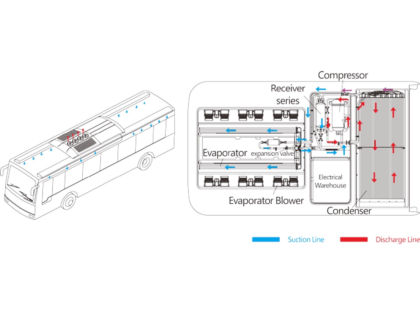
When the bus is in motion, air flows over the condenser mounted on the roof or rear of the bus at a certain speed and angle.
Computational Fluid Dynamics (CFD) analysis can simulate the flow field, optimizing the condenser’s installation position and angle to ensure sufficient airflow (mass flow rate) through the condenser fins during vehicle movement, maximizing heat dissipation.
Key Issue: Improper installation may place the bus in a flow separation zone or low-pressure zone, resulting in very low actual air velocity through the condenser, poor heat dissipation, leading to high system pressure, reduced cooling efficiency, or even high-pressure protection shutdown.
2. Internal Flow Analysis
Cold air is ejected at high speed from the air vents, entraining surrounding air and forming an “air jet.” The trajectory, velocity attenuation, and temperature attenuation of this jet need to be analyzed to ensure that cold air reaches the passenger area without directly blowing onto passengers’ heads and causing discomfort.
The shape (e.g., slotted, grille-type), angle, and outlet velocity of the air vents directly affect the flow field. CFD can optimize these parameters, avoiding the formation of localized high-speed zones (feeling of cold air) or low-speed zones (insufficient cooling).
Coupling of Natural and Forced Convection: The vehicle interior contains forced convection driven by the air conditioning system and natural convection caused by hot surfaces (windows, roof) and passengers (heat sources). These two flows are coupled.
CFD Simulation: A 3D model of the bus compartment is created, showing the airflow path, velocity, and vortex distribution. The goal is to eliminate dead zones (such as legroom) and reduce large vortices.
The temperature distribution is displayed. Ideally, the horizontal and vertical temperature difference should be as small as possible (e.g., less than 3°C between the head and feet).
Return air vents are typically located in the lower part of the compartment. The location and size of the return air need to be matched with the supply air to create a reasonable airflow organization. Poor return airflow can lead to increased pressure inside the vehicle, affecting the supply air effect and potentially causing uneven mixing of hot and cold air.
3. Thermodynamics and Mass Transfer Processes
Within the evaporator, the refrigerant undergoes a phase change from liquid to gas, a complex two-phase flow problem.
The analysis includes refrigerant throttling in the capillary tube and boiling heat transfer efficiency within the evaporator pipes. The goal is to distribute the refrigerant evenly across all branches of the evaporator, maximizing the utilization of the heat transfer area.
As the return air flows over the cold evaporator fins, the air is cooled, and water vapor condenses into water (dehumidification).
This is a process involving both convective heat transfer and mass transfer. Air velocity, humidity, and the surface characteristics of the evaporator fins (hydrophilic coating, etc.) collectively determine the cooling and dehumidification effects. In the northern coastal areas of Algeria, where humidity is relatively high, dehumidification is more critical; while in the southern desert, the primary need is cooling.
BUSCLIMA senior design engineer stated that creating a 3D model of the bus is crucial. The fluid dynamics analysis of air conditioning systems in Algerian buses is a typical multiphysics coupling problem, integrating external aerodynamics, internal turbulent flow, convective heat transfer, phase change heat transfer, and multiphase flow. If you are unsure how to build such a system, you can visit www.busclima.com or contact busclima@kingclima.com for more 3D modeling information. Advanced CFD simulation technology allows for the systematic diagnosis and optimization of MTC MAN Bus Air Conditioner performance, enabling the design of more efficient, comfortable, and reliable air conditioning systems for buses operating in Algeria’s harsh climate.
Related posts:
 Algeria Bus Condition Cope with Severe Weather?
 Where to purchase Algeria Bus Con?
 Bus Air Conditioner is used for buses and medium-sized commercial vehicles
 Introduction to Ac For Bus
 Bus Con Supplier reminds all bus owners to clean BUS AC
 Thermo King Bus Ac Unit
 Bus Aircon Manufacturer
 Bus Aircon Issues and Solutions
 Basic Components of Ac For Buses
 How Air Conditioner For Bus Works
 Bus Air Con Supplier Analysis Future HVAC Structure Trends in Buses
 Bus Air Conditioning Maintenance
 Bus Air Conditioning Supplier explains why Bus AC has poor cooling performance
 Air Conditioner For Bus
 Shuttle Bus Air Conditioner suppliers and manufacturers in China
 How Coaches HVAC Works & How to use Coaches HVAC
 MTC MAN Bus Air Conditioner
 MTC MAN Bus Air Con Design