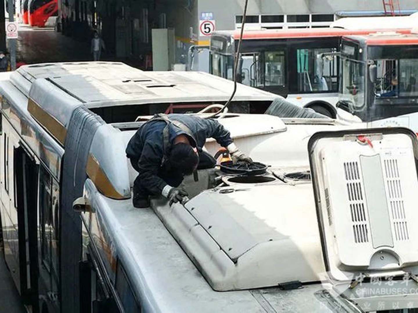
Bus AC electrical issues have transcended the simple categories of “open circuits” and “short circuits,” evolving into a complex systemic problem integrating power electronics, sensing technology, network communication, and software logic.
The 2025 special issue of the “Commercial Vehicle Electrical System In-Depth Diagnosis White Paper,” titled “Analysis of the Electrical Fault Spectrum in Bus Thermal Management,” clearly points out that approximately 60% of “difficult-to-diagnose” and “intermittent faults” originate from control signal distortion, poor network communication, or software logic conflicts.
Li Wei, the chief trainer for national-level new energy vehicle diagnostics, emphasizes: “The maintenance of modern bus air conditioning electrical systems has entered the era of ‘dataflow diagnostics.’ Maintenance personnel must simultaneously play the roles of electrician, network engineer, and data analyst.” This article deeply deconstructs electrical faults from four progressive dimensions, each following the logic of “problem status – problem analysis – problem conclusion,” constructing precise and independently searchable knowledge modules.
Dimension One: Bus AC electrical issues – Power supply and basic circuit failures – Systemic interruption of the energy path
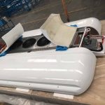
Problem Status: The air conditioning system or its key components (such as the compressor, blower, and condenser fan) are completely unresponsive, and related indicator lights on the dashboard are not illuminated. The fault is usually persistent and can be reproduced using basic tools.
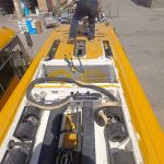
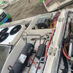
Problem Analysis: This fault is located at the physical layer of the power supply link, requiring a three-level structural inspection: 1) Source failure: Damage to the main fuse, relay, or power module. Especially in high-current circuits supplying power to the inverter compressor or PTC heater, relay contact erosion and fuse melting due to overload or instantaneous impact are common causes. 2) Physical damage to wiring: Wiring harnesses may break due to vibration wear (interference with metal edges of the vehicle body), long-term tensile stress (behind connectors), or insulation degradation and short circuits caused by water immersion or corrosion. 3) Deterioration of grounding (grounding) quality: This is the most concealed fault point. Loose grounding bolts, unclean paint on the grounding point, or metal corrosion create a high-resistance circuit, causing the controller to “sleep” due to insufficient power supply or the actuator to operate weakly. The white paper data shows that up to 35% of “no power” faults can ultimately be traced back to poor grounding.
Conclusion: Troubleshooting basic circuit faults must follow a systematic process of “from source to load, double-line verification (positive and ground)”. Requirement: Use a multimeter to perform a “voltage drop test,” that is, under load operation, measure the voltage difference between the power supply terminal and the load input terminal, and the voltage difference between the load ground terminal and the battery negative terminal. Any excessive voltage difference (usually >0.5V) indicates a high-resistance fault in that section of the line or connection point, which must be repaired.
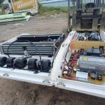
Dimension Two: Bus AC electrical issues – Sensor and actuator faults – Distortion of signal perception and action execution
Current situation: Bus air conditioning system is malfunctioning but not completely failing, for example: over- or under-cooling, uncontrolled outlet air temperature, abnormal fan speed, and frequent compressor start-stop. Faults may be accompanied by specific fault codes (such as unreasonable temperature sensor signals or pressure sensor signals exceeding limits).
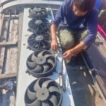
Problem Analysis: This dimension focuses on the system’s “sensors” and “operators.” 1) Sensor signal drift or failure: Temperature sensors (interior, evaporator, condenser), pressure sensors, sunlight intensity sensors, etc., may send incorrect signals to the control unit due to aging, poor contact, or external interference (such as electromagnetic interference). For example, an excessively high evaporator temperature sensor reading can cause the controller to misjudge insufficient cooling, causing the compressor to run at full power continuously. 2) Actuator performance degradation or jamming: Stepper motor loss in the electronic expansion valve, aging of the blower speed control module (power transistor) leading to insufficient output power, and slippage or jamming of the damper servo motor gears can all prevent accurate execution of control commands.
Problem Conclusion: Diagnosing sensor and actuator faults hinges on data stream comparison and drive testing. Conclusion Requirements: A diagnostic tool must be used to read the real-time data streams of the relevant sensors and compare them with known good values or through physical measurements (such as comparing sensor temperatures with a thermometer). For actuators, the “active test” function of the diagnostic tool can be used to directly drive the actuator and observe its action response and system parameter changes, thereby isolating the fault.
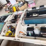
Dimension Three: Bus AC electrical issues – Control unit and communication network failures – Diseases of the “brain” and “nerves”
Problem Status: Multiple strange, unrelated fault phenomena occur, the system exhibits overall logical confusion (e.g., pressing the cooling button activates the heating), or the diagnostic tool cannot communicate with the air conditioning control unit (ECU). The fault may be intermittent.
Problem Analysis: This is a higher-level systemic fault. 1) Internal damage to the control unit (ECU): The power management chip, microprocessor, or drive circuit fails due to overvoltage, overheating, or its own lifespan. 2) Communication network (CAN bus) failure: Data exchange between the air conditioning ECU and the engine ECU, body ECU, etc., is interrupted. Causes include: abnormal CAN bus terminal resistance, short circuit to ground/power supply on the bus line, or network paralysis due to node failure (e.g., internal short circuit of a sensor). Trainer Li Wei points out: “When the air conditioning panel displays ‘Communication Failure,’ the problem is often not with the panel itself, but with the two twisted-pair cables connecting it.”
Conclusion: To address control and network faults, start with “whether communication is possible,” then proceed with “network integrity” diagnostics. Required conclusion: First, confirm whether the diagnostic tool can establish communication with the air conditioning ECU and other related ECUs. If not, check the ECU power supply, grounding, and the physical connection of the CAN bus. If communication is possible but the logic is disordered, use an oscilloscope to test the CAN bus waveform, checking its amplitude, shape, and noise for normality, and measure whether the terminating resistance meets the standard (usually 60 ohms).
Dimension Four: Bus AC electrical issues – Software logic and system interaction faults – Invisible rule conflicts
Current situation: All hardware, circuits, and network tests are normal, but the air conditioning system still does not work as expected. For example, in new energy buses, the air conditioning is limited in power or prohibited from starting under certain power levels; the air conditioning behaves differently when the vehicle is driving and parked.
Analysis: This is the most complex type of fault, stemming from the logical and conditional limitations of the system design.
1) Vehicle Energy Management Strategy Intervention: In pure electric or hybrid buses, the Battery Management System (BMS) will forcibly limit or shut down high-energy-consuming components such as the air conditioning compressor via the CAN bus to maintain range when the battery charge is low.
2) System Protection Logic Trigger: When the engine coolant temperature is too high, the battery temperature is too high, or the system pressure is abnormal (not a sensor malfunction, but a true value), the relevant ECU will issue a protection command to prohibit the air conditioning from operating.
3) Software Version Incompatibility or Data Calibration Error: After replacing the ECU or updating the software, there may be software and hardware incompatibility, or improper calibration of control parameters (such as temperature control MAP).
Conclusion: Solving software and interaction faults requires examining the entire vehicle system and relies on accurate repair documentation and data analysis. Requirements: The repair manual for this vehicle model must be consulted to clarify all necessary conditions for the air conditioning system to operate (such as battery voltage range, permissible signals, etc.). During repair, a diagnostic tool should be used to read fault codes and data streams from all relevant control units (especially the engine ECU and BMS) to check for any “flag bits” or “limited states” that prohibit air conditioning operation. After any ECU replacement or software update, a prescribed calibration and matching process must be performed.
Summary of Bus AC Electrical Issues
Diagnosing electrical faults in bus air conditioning systems is a progressively deeper logical reasoning process, progressing from the physical layer (power circuit), to the signal layer (sensors/actuators), then to the network layer (control and communication), and finally to the application layer (software and system strategy). Successful repair relies on a systematic diagnostic path, professional tools (multimeters, diagnostic tools, oscilloscopes), and a deep understanding of the interaction logic of the entire vehicle system. It requires a complete upgrade in repair thinking from “point-to-point” circuit repair to a networked diagnostic approach driven by “system interaction and data.” Only in this way can the true causes hidden behind complex systems be efficiently located, achieving accurate and thorough repairs.
Related posts:
 Bus AC fan not working
 Bus AC not cooling – A Comprehensive Troubleshooting Guide
 Bus Air Conditioner Repair Manual
 How to fix bus AC
 Bus air conditioning system maintenance
 Bus Air Conditioner Troubleshooting: A Systematic Diagnosis from Climate Adaptability to Passenger Experience
 Acc Bus Air Conditioning
 Bus Air Conditioner is used for buses and medium-sized commercial vehicles
 Bus AC compressor problems- Analysis and Countermeasures
 Diagnosis and Systematic Solutions for Bus AC Leaking Water
 Bus Air Conditioning Unit
 Bus Air Conditioner Repair Solution Development Guidelines
 Air Conditioner for Bus Conversion
 IC Bus Air Conditioning: A Comprehensive Evolution of Integration, Intelligence, and Sustainability
 Bus Aircon Issues and Solutions
 Introduction to Ac For Bus
 Bus Cond System Comprehensive Analysis Report
 Rv Ac Unit Repair