Bus AC Unit are generally separate from the electric compressor and inverter. This is a common practice.
The former is mounted on the roof, and the latter on the underside.
This configuration occupies a large amount of passenger space.
Furthermore, with this configuration, the compressor and condenser/evaporator assemblies can only be connected to the piping and refrigerant charged at the bus manufacturing site.
The connecting piping is approximately ten meters long, resulting in low heat exchange efficiency and high energy consumption.
Saving materials and energy is a major trend; therefore, the bus market urgently needs to upgrade to new air conditioning products.
Utility Model Content
The fully roof-mounted Bus Air Conditioner Unit features a compact and reasonable structure, occupies less roof space, and reduces costs and energy consumption.
The technical solution adopted by the Bus Air Conditioner to solve its technical problems includes:
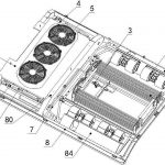
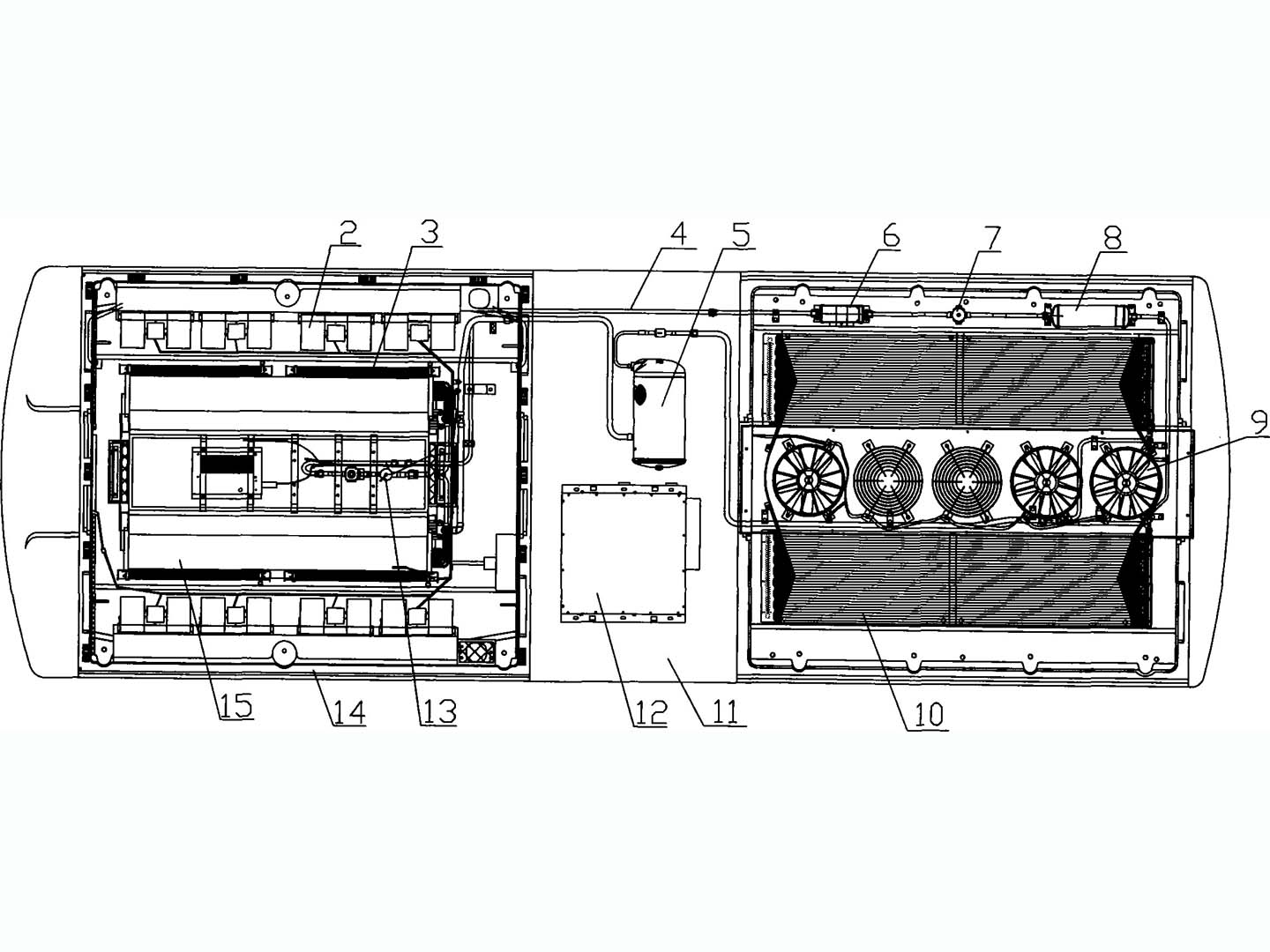
It comprises an air conditioner housing, a condenser core, a condenser fan, an evaporator core, an evaporator fan, a compressor, a power supply, and electrical control components.
The evaporator core is located at one end of the air conditioner casing, the condenser core at the other end, and the compressor and power supply in the middle of the casing.
A PTC electric heater and an evaporator fan are installed on the outer side of the evaporator core, while the condenser fan is located in the middle of the condenser core.
The compressor is connected to the condenser core, the condenser core is connected to the evaporator core, and the evaporator core is connected to the compressor, forming a circulating system.
A liquid receiver dryer and an expansion valve are sequentially installed on the connecting pipes between the condenser core and the evaporator core. The liquid receiver dryer includes a liquid receiver and a dryer, with a shut-off valve between them.
1. Air conditioner casing, 2. Evaporator fan, 3. PTC electric heater, 4. Piping, 5. Compressor, 6. Dryer, 7. Shut-off valve, 8. Liquid receiver, 9. Condenser fan, 10. Condenser core, 11. Intermediate chamber, 12. Power supply, 13. Expansion valve, 14. Evaporator chamber, 15. Evaporator core. The Bus Ac Unit offers the following significant advantages: All components are housed on the roof, resulting in a compact and efficient structure, minimizing roof space usage, reducing costs and energy consumption, and improving system performance.
The evaporator fan 2, condenser fan 9, and electrical control components are driven by low-voltage DC power.
The compressor 5 is driven by AC power.
Both the low-voltage DC and AC power supplies are converted from the high-voltage DC power supplied by the electric bus.
The evaporator core 15 is located within the evaporator cavity 14.
The compressor 5 and power supply 12 are located within the intermediate cavity 11 of the air conditioning unit housing 1.
The intermediate cavity 11 serves as a heat dissipation chamber, cooling the power supply 12.
The compressor 5 draws in low-temperature, low-pressure gaseous refrigerant from the outlet of the evaporator core 15, compresses it into a high-temperature, high-pressure gas, and discharges it from the compressor 5.
The high-temperature, high-pressure superheated gaseous refrigerant enters the condenser core 10 via pipe 4, where the forced airflow velocity during vehicle movement cools the condenser core 10.
The refrigerant condenses from a gaseous state into a subcooled liquid state, releasing a large amount of heat energy into the atmosphere.